Service News
Copyright By FCA Italy S.p.A. - Printed 26/10/2016 – Esc.1885


Ducato (250 and 290)


All Euro5 models with left-hand drive and manual air conditioning (Opt.025)
50
001.16
5040 1 861 RD FAN SPEED CONTROL
Failed operation - Service Solution


Cancels and replaces SN 50.001.16 of 05/02/2016 due to Spare Part availability table update.

CLAIMED FAULT

The air conditioner fan only works at one speed.

TECHNICAL CAUSE

Damage to the wiring due to overcurrent.

OPERATIONS IN PRODUCTION

Adoption of new wiring with an additional relay to manage the 4th passenger compartment fan speed.

IMPLEMENTATION OF MODIFICATION


Version


Plant


Line


Chassis no.


Organisation No.


Ducato (290)


Sevel


-


2915236


2077670

OPERATIONS AT THE DEALERSHIPS

DEALERSHIP BEHAVIOUR STANDARDS TOWARDS THE CUSTOMER

  • Once the Customer's claimed fault is confirmed, reassure the Customer that the fault will be solved by replacing the air conditioner wiring with a new one equipped with a relay specifically to manage the maximum passenger compartment air speed.
  • After completing the operation, illustrate what has been done and ensure that the Customer is satisfied.

Service Solution

Once the Customer's claimed fault is confirmed, replace the air conditioner wiring with a new one equipped with a relay specifically to manage the 4th passenger compartment air speed according to the Operating Cycle below.

OPERATION CYCLE

Referring to the procedure (Op) in the Service Manual, replace the manual air conditioner wiring with a new one equipped with a relay for the 4th speed, as follows.

  • Turn the ignition key to the STOP position and remove it.
  • Remove the battery cover (Op.5530B54)
  • Disconnect the negative and positive battery terminals and insulate them.
  • Remove the compartment from the dashboard (Op.7040A18).
  • Remove the lower dashboard under-compartment cover (Op.7040A19).
  • Remove the central under-dashboard cover (Op.7040A60).
  • Depending on the version, remove either the central dashboard compartment assembly (Op.7040A31) or the cup holder and its support (Op.7040F01).
  • Remove the radio (Op.5570T80).
  • Remove the radio support (Op.5570T10).
  • Depending on the version, remove either the central upper compartment door (Op.7040A14) or the document holder (Op.7040A71).
  • Remove both the dashboard central air vents (Op.5010C31)
  • Remove the switch unit on the dashboard (Op.7040A56)
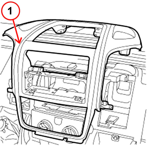
  • Remove the central trim on the instrument panel (1 – Fig. 1) (Op.7040A25).

Fig. 1


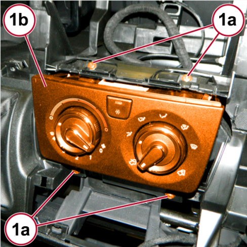
  • Undo the fixing screws (1a - Fig. 2) and release the control unit with manual air conditioner controls (1b) from the dashboard trim, without removing it.

Protect the plate to prevent any damage during removal and reinstallation.

Fig. 2


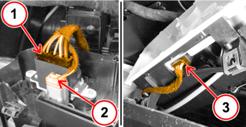
  • Disconnect the electrical connections (Fig.3) and put the control unit aside.

1 - fan speed switch

2 - illumination bulbs

3 - compressor on control button

Fig. 3


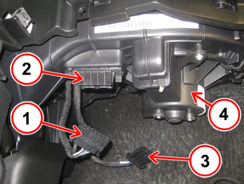
  • Disconnect the electrical connection (1 - Fig. 4) from the fan resistor (2).
  • Disconnect the electrical connection (3 - Fig. 4) from the fan (4).

Fig. 4


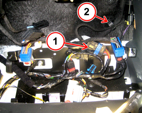
  • Disconnect the front wiring/manual air conditioner junction connection (1 – Fig. 5) and free the wiring from the retaining clip (2).

Fig. 5


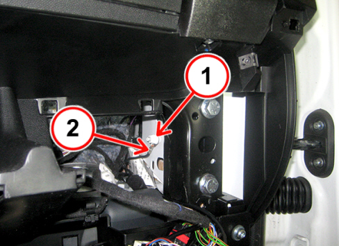
  • Undo the fixing nut (1 – Fig. 6) and disconnect the earth lead (2).

Fig. 6


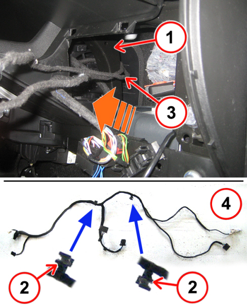
  • Access the dashboard support bracket (1 – Fig. 7) in the front area and disconnect the press-in clips (2) that hold the wiring to the air duct fin.
  • Remove the air conditioner wiring (4 – Fig. 7) from the lower central area, helping the earth and front wiring junction cables (3) to come out from behind the dashboard support bracket (1).

Fig. 7


  • Replace the manual air conditioner wiring with the new one taken from the Spare Parts Dpt. The new wiring must follow the same path and be secured with the same fasteners as the wiring removed.
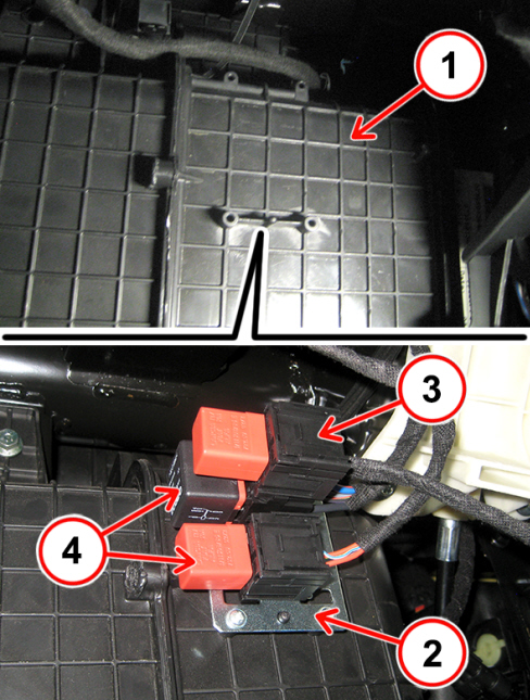
  • For the cars not equipped with a supplementary heater/air conditioner, fix the relay switch holder bracket (2) to the air conditioner box (1 – Fig. 8) and tie the 4th passenger compartment air speed relay switch (3) to the bracket.
  • For the cars equipped with the supplementary heater/air conditioner, which already have the relay switch holder bracket (2), tie the 4th passenger compartment air speed relay switch (3) to the two existing relay switches (4) (passenger compartment fan relay switch and additional heater relay switch).

Fig. 8


  • Then, refit the removed components performing the removal operations in the reverse order.

PARTS AVALABILITY


Version


Description


Order no.


Qty


All models in question with manual air conditioner (Opt. 025)


Wiring


1385659080


1


All models in question with manual air conditioner (Opt. 025)


Relay switch


11129885


1


All models in question with manual air conditioner (Opt. 025) and supplementary heater (Opt. 205) or with provision for the supplementary heater (Opt. 133)


Wiring


1385658080


1


All models in question with manual air conditioner (Opt. 025) and supplementary air conditioner (Opt. 204) or with provision for the supplementary air conditioner Opt.4GT)


Wiring


1385655080


1


All models in question without supplementary heater


Relay switch holder bracket


1372774080


1


All models in question without supplementary heater


Relay switch holder fixing screws


16083507


4 (*)

(*) Every pack contains 10 bolts

CLAIM REPORT DATA


Version


Operation


Part


Fault


Position


Time allowance


All models in question


5040186


1


RD


-


1.70