
|
 Removing
(
Refitting Removing
(
Refitting )
)
- Position the vehicle on the lift. Op. 5530B54 - Disconnect the negative battery terminal.
|
|
|
|
Op. 7055B91 Op. 7055B51 Op. 7055B56 |
|
|
Op. 7055A43 Op. 7210E10 Op. 7210E09 Op. 7210E11 Op. 7025A34 |
|
Op. 7210A15 |
|
|
Op. 1064B35 PRESSURIZED AIR SUPPLY PIPE TO WASTE GATE VALVE - R.R. |
|
Op. 1064B36 PRESSURIZED AIR SUPPLY PIPE TO WASTE GATE ACTUATOR - R.R. |
|
Op. 1064B44 WASTE GATE VALVE ACTIVATION SOLENOID VALVE - R.R. |
|
Op. 1064B30 WASTEGATE SOLENOID VALVE MOUNTING BRACKET - R.R. |
|
|
|
|
Op. 1048A42 SLEEVE FROM FLOW METER TO TURBO CHARGER AIR INLET PIPE - R + R |
|
|
Op. 1008B10 POWER UNIT FRONT SUPPORT FLEXIBLE MOUNTING (TIMING SIDE) - REPLACE |
|
|
|
Op. 1032B10 TOOTHED TIMING BELT - R.R. FOR TIMING OR REPLACEMENT |
|
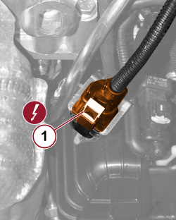 |
1. Disconnect the electrical connection for the Lambda sensor. |
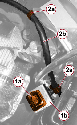 |
1. Release the oxygen sensor connector (1a) from the mounting bracket (1b). 2. Open the retaining clips (2a) and release the oxygen sensor wiring (2b). |
|
|
Op. 1040B28 DUPLEX FUEL SUPPLY/RETURN PIPE TO PRESSURE PUMP - R.R. |
|
|
|
Op. 1080D28 OIL VAPOUR RECOVERY PIPE BETWEEN SEPARATOR AND TURBO - R.R. |
|
Op. 1088D04 DEGASSING PIPE FROM THERMOSTAT TO ENGINE COOLANT RESERVOIR - R.R. |
|
Op. 1084B40 ENGINE OIL DELIVERY PIPE TO TURBOCHARGER - R + R |
|
|
Op. 1060F36 PIPES (ALL) FROM FUEL MANIFOLD TO INJECTORS - R.R. |
|
|
|
|
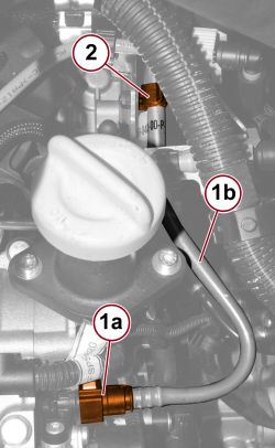 |
2. Open the retaining clip and move the pipe to one side. |
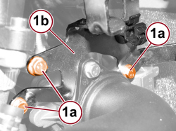 |
1. Undo the screws (1a) and remove the wiring and pipe mounting bracket (1b). |
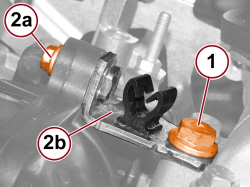 |
1. Undo the camshaft housing fixing screw. 2. Undo the air chamber fixing screw (2a) and remove the camshaft housing connection bracket (2b). |
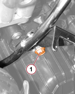 |
1. Undo the oil dipstick tube mounting bracket fixing screw.
|

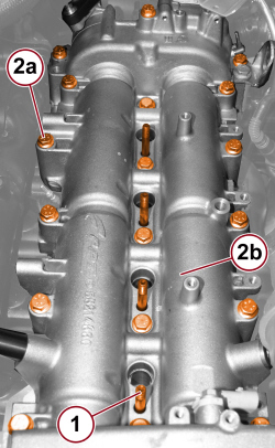 |
1. Loosen and remove the injector retaining bracket fixing studs. 2. Undo the screws (2a) and remove the camshaft housing (2b).
|
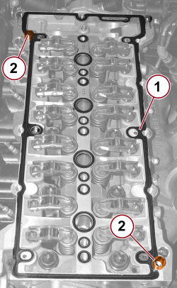 |
1. Remove the seal. 2. Remove the locating bushes. |
 |
Refitting
(
Removing
)
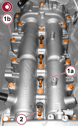
- Place the camshaft housing locating bushes on the cylinder head. - Place the camshaft housing gasket in position. 1. Position the complete camshaft housing (1a) in place and secure it by tightening the screws (1b) to the prescribed torque.
2. Tighten the injector retaining bracket fixing studs. |
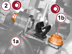 |
- Tighten the oil dipstick tube mounting bracket fixing screw. 1. Place the connection bracket (1a) in position and tighten the camshaft housing fixing screw (1b) to the prescribed torque.
2. Tighten the air chamber fixing screw to the prescribed torque.
|
|
|
- Place the pipe and wiring mounting bracket in its position and tighten the fixing screws to the prescribed torque. - Connect the quick connector for the brake servo vacuum pipe and close the retaining clip. |
|
|
|
|
|
Op. 1060F36 PIPES (ALL) FROM FUEL MANIFOLD TO INJECTORS - R.R. |
|
|
Op. 1084B40 ENGINE OIL DELIVERY PIPE TO TURBOCHARGER - R + R |
|
Op. 1088D04 DEGASSING PIPE FROM THERMOSTAT TO ENGINE COOLANT RESERVOIR - R.R. |
|
Op. 1080D28 OIL VAPOUR RECOVERY PIPE BETWEEN SEPARATOR AND TURBO - R.R. |
|
|
|
Op. 1040B28 DUPLEX FUEL SUPPLY/RETURN PIPE TO PRESSURE PUMP - R.R. |
|
- Engage the oxygen sensor connector with the mounting bracket and engage the wiring with the retaining clips. - Connect the electrical connection for the Lambda sensor.
|
|
|
Op. 1032B10 TOOTHED TIMING BELT - R.R. FOR TIMING OR REPLACEMENT |
|
|
|
Op. 1008B10 POWER UNIT FRONT SUPPORT FLEXIBLE MOUNTING (TIMING SIDE) - REPLACE |
|
|
Op. 1048A42 SLEEVE FROM FLOW METER TO TURBO CHARGER AIR INLET PIPE - R + R |
|
|
|
|
Op. 1064B30 WASTEGATE SOLENOID VALVE MOUNTING BRACKET - R.R. |
|
Op. 1064B44 WASTE GATE VALVE ACTIVATION SOLENOID VALVE - R.R. |
|
Op. 1064B36 PRESSURIZED AIR SUPPLY PIPE TO WASTE GATE ACTUATOR - R.R. |
|
Op. 1064B35 PRESSURIZED AIR SUPPLY PIPE TO WASTE GATE VALVE - R.R. |
|
|
|
Op. 7210A15 |
|
Op. 7025A34 Op. 7210E11 Op. 7210E09 Op. 7210E10 Op. 7055A43 |
|
|
Op. 7055B56 Op. 7055B51 Op. 7055B91 |
|
|
|
- Connect the negative battery terminal.
Op. 5530B54 - Remove the vehicle from the lift. |