DESCRIPTION OF COMPONENTSInjection control unit (EDC 17C49 common rail)This is fitted in the engine compartment on the right side. The control unit is the flash EPROM type, i.e. it can be reprogrammed from the outside without operations to the hardware. The injection control unit incorporates the absolute pressure sensor. PIN OUT 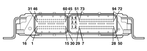
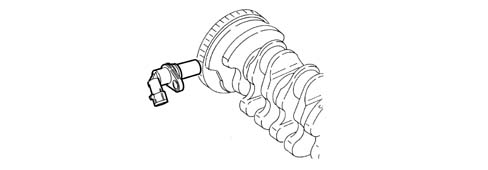
Connector A (vehicle wiring) 1 - Battery positive 2 - Earth 3 - Battery positive 4 - Earth 5 - Battery positive 6 - Earth 7 - Oxygen sensor heater control (only for versions with oxygen sensor) 8 - N.C. 9 - N.C. 10 - N.C. 11 - Oil vapour heating resistance 12 - Air conditioning linear pressure sensor (+) 13 - N.C. 14 - Differential pressure sensor (DPF) (+) (only for versions with DPF) 15 - N.C. 16 - Potentiometer 1 on accelerator pedal (+) 17 - Potentiometer 2 on accelerator pedal (+) 18 - N.C. 19 - Air flow rate sensor signal 20 - Earth (flow meter) 21 - Air temperature sensor (flow meter) 22 - N.C. 23 - N.C. 24 - CAN (high channel) 25 - CAN (low channel) 26 - Heater plugs activation 27 - Engine cooling fan 3rd level 28 - Main relay control negative signal 29 - N.C. 30 - Water in diesel filter sensor signal 31 - N.C. 32 - N.C. 33 - N.C. 34 - Air conditioning linear pressure sensor (-) 35 - N.C. 36 - DPF differential pressure sensor earth (only for versions with DPF) 37 - N.C. 38 - Potentiometer 1 on accelerator pedal (-) 39 - Potentiometer 2 on accelerator pedal (-) 40 - N.C. 41 - N.C. 42 - N.C. 43 - Clutch signal 44 - Reversing switch signal 45 - N.C. 46 - N.C. 47 - N.C. 48 - Engine cooling fan 1st level 49 - Engine cooling fan 2nd level 50 - N.C. 51 - N.C. 52 - N.C. 53 - N.C. 54 - 15/50 signal from ignition switch 55 - N.C. 56 - Air conditioning linear pressure sensor signal 57 - N.C. 58 - DPF differential pressure sensor signal (only for versions with DPF) 59 - N.C. 60 - Potentiometer 1 on accelerator pedal signal 61 - Potentiometer 2 on accelerator pedal signal 62 - N.C. 63 - Oxygen sensor voltage signal (only for versions with oxygen sensor) 64 - Oxygen sensor supply current (only for versions with oxygen sensor) 65 - Diesel temperature sensor (-) 66 - N.C. 67 - Heater plug control unit diagnosis 68 - N.C. 69 - N.C. 70 - N.C. 71 - N.C. 72 - N.C. 73 - N.C. 74 - N.C. 5 V sensor supply 1 75 - Low pressure pump relay control 76 - N.C. 77 - N.C. 78 - EGR exchanger actuator N.C. 79 - N.C. 80 - N.C. 81 - N.C. 82 - N.C. 83 - Exhaust gas temperature sensor earth 2 (only for versions with DPF) 84 - Exhaust gas temperature sensor signal 2 (only for versions with DPF) 85 - Oxygen sensor earth (only for versions with oxygen sensor) 86 - Oxygen sensor current adjustment (only for versions with oxygen sensor) 87 - Diesel temperature sensor signal 88 - Signal + contact on brake pedal (NA) 89 - Pre-heating control unit reference earth 90 - N.C. 91 - Oil vapour heating relay control negative signal 92 - N.C. 93 - Wastegate solenoid valve control 94 - Compressor engagement relay control negative signal Connector B (engine wiring) 1 - Cylinder no. 3 injector (+) 2 - Cylinder no. 2 injector (+) 3 - N.C. 4 - N.C. 5 - Oil level sensor signal control unit (+) 6 - Oil level sensor signal control unit (+) 7 - N.C. 8 - N.C. 9 - EGR position sensor power supply 10 - Air pressure/temperature sensor (+) 11 - Fuel pressure sensor (+) 12 - 13 - Timing sensor (+) 14 - Timing sensor signal 15 - Fuel pressure regulator (+) 16 - Cylinder no. 1 injector (+) 17 - Cylinder no. 4 injector (+) 18 - N.C. 19 - EGR heat exchanger by-pass actuator 20 - Throttle valve actuator control 21 - Throttle valve position sensor signal 22 - Throttle valve position sensor earth 23 - N.C. 24 - EGR position sensor earth 25 - Air temperature/pressure sensor (-) 26 - Fuel pressure sensor (-) 27 - N.C. 28 - Timing sensor (-) 29 - N.C. 30 - N.C. 31 - Cylinder 3 injector (-) 32 - Cylinder 1 injector (-) 33 - N.C. 34 - N.C. 35 - EGR solenoid valve (-) 36 - Alternator D+ signal 37 - N.C. 38 - N.C. 39 - EGR position sensor signal 40 - Air pressure/temperature sensor (pressure signal) 41 - Fuel pressure sensor signal 42 - N.C. 43 - N.C. 44 - Engine rpm sensor (-) 45 - N.C. 46 - Cylinder 2 injector (-) 47 - N.C. 48 - Cylinder 4 injector (-) 49 - N.C. 50 - EGR solenoid valve (+) 51 - N.C. 52 - N.C. 53 - N.C. 54 - Low engine oil pressure 55 - Air pressure/temperature sensor (temperature signal) 56 - N.C. 57 - Engine coolant temperature sensor signal 58 - Engine coolant temperature sensor (-) 59 - Engine rpm sensor (+) 60 - Fuel pressure regulator (-) RPM SENSORCharacteristicsIt is fitted on the cylinder block, facing the toothed wheel on the crankshaft. It is the inductive type, in other words it operates through the variation in the magnetic field produced when the flywheel teeth (60 – 2) pass by. The injection control unit uses the RPM signal to:
OperationThe changeover from full to empty determined by the presence or absence of a gap brings about a magnetic flux change sufficient to generate an induced alternating voltage proportional to the number of teeth on the ring (or phonic wheel). The frequency and amplitude of the voltage sent to the electronic control unit provides it with details of crankshaft angular speed. 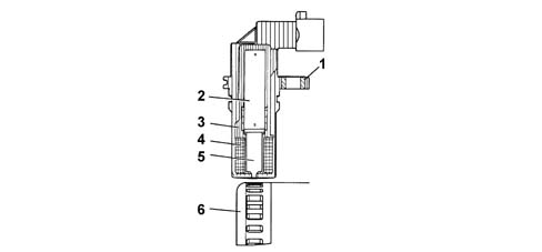
1 - Brass bush 2 - Permanent magnet 3 - Plastic sensor casing 4 - Coil winding 5 - Core 6 - Ring gear or phonic wheel 7 - Coaxial paired cable or electrical connection The recommended distance (gap), between the end of the sensor and flywheel, to produce correct signals, should be between 0.8 and 1.5 mm. This distance is not adjustable.Therefore, if the gap is found to be outside the tolerance limits, check the condition of the sensor and phonic wheel. 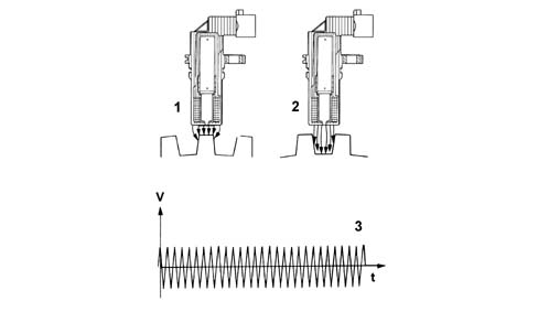
1 - Maximum magnetic flux 2 - Minimum magnetic flux 3 - Induced alternating voltage trend CAM ANGLE SENSORCharacteristicsThis Hall effect sensor is fitted on the cylinder head, facing the camshaft drive pulley. A tooth on the pulley allows the timing sensor to indicate the engine timing position. The injection control unit uses the timing sensor signal to identify T.D.C. at the end of compression. 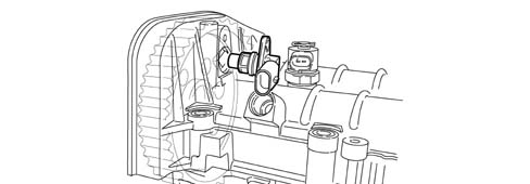
OperationA current-carrying semiconductor layer immersed in a normal magnetic field (force lines at right angles to current direction) generates a potential difference known as a Hall voltage at its terminals. If current intensity remains constant, the generated voltage depends on magnetic field intensity alone.Periodic changes in magnetic field intensity are sufficient to generate a modulated electrical signal with frequency proportional to the speed of magnetic field change. To produce this change, a tooth on the inner part of the pulley periodically moves close to the sensor. 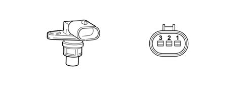
1- Earth 2 - Signal 3 - Supply INTAKE AIR TEMPERATURE AND EXCESS PRESSURE SENSORCharacteristicsThe excess pressure and intake air temperature sensor is an integral component designed to measure the pressure and the temperature of the air inside the intake manifold. It is fitted on the intake manifold and has the task of notifying the injection control unit to:
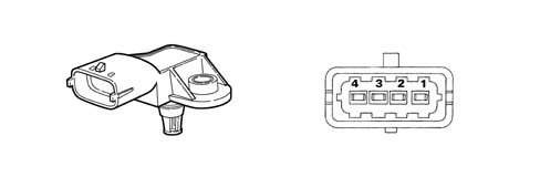
1- Earth 2 - Air temperature signal 3 - 5 Volt (from ECU) 4 - Turbocharging pressure output signal ENGINE COOLANT TEMPERATURE SENSORCharacteristicsThis is fitted on the thermostat and detects coolant temperature by means of a dual NTC thermistor with negative resistance coefficient. One NTC thermistor sends a signal to the injection control unit, whilst the other sends a signal to the temperature gauge and the warning light in the instrument panel. 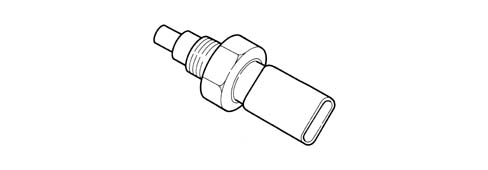
The sensor is designed using semiconductor technology.In other words, the resistance level drops if the sensor element temperature increases as the coolant temperature increases. The non-linear change in resistance is greater for changes at low temperatures and lesser for changes at high temperatures. AIR FLOW METER WITH BUILT IN AIR TEMPERATURE SENSORCharacteristicsThe digital air flow meter is located on the air intake hose and is a hot film type meter. 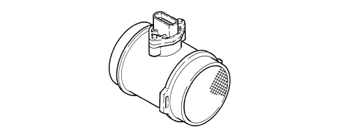
Pin out 1 - 12 V power supply 2 - Earth 3 - Air temperature output signal 4 - Air flow rate output signal The NTC intake air temperature sensor is built into the air flow meter.
OperationThe operating principle is based on a heated diaphragm placed in a measuring duct through which the inlet air entering the engine flows. The hot film diaphragm is kept at a constant temperature (about 120°C higher than the temperature of the incoming air) by the heating resistance. The air mass that flows through the measurement channel tends to remove heat from the membrane.A certain amount of current must therefore flow through the heater coil in order to maintain the membrane at a constant temperature. This current is measured by the electronic circuit in the plug-in and is proportional to the mass of air flowing through. This leads to the following advantages: - lower response time - improved measurement precision. The presence of an quartz oscillator on the printed circuit allows the flow meter to measure the air flow rate directly. FUEL PRESSURE SENSORCharacteristicsIt is fitted at the end of the common rail and its function is to provide the injection control unit with a feedback signal to enable it to:
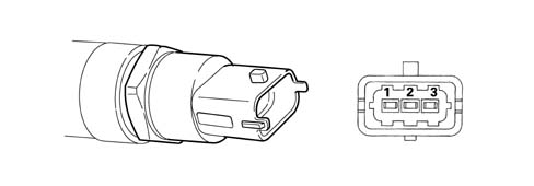
1- Earth 2 - Output signal 3 - Supply ACCELERATOR PEDAL POTENTIOMETERConstruction specificationsThe sensor consists of a case secured to the accelerator pedal; the case contains an axially-located shaft connected to two potentiometers: a main one and a safety one. A coil spring on the shaft guarantees the correct resistance to pressure whilst a second spring ensures the return on release. 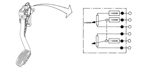
OperationThe accelerator pedal position is transformed into an electrical voltage signal and is sent to the injection control unit from the potentiometer connected to the associated pedal. The accelerator pedal position signal is processed together with the information relating to the engine rpm in order to obtain the injection times and the pressure. MOTORISED THROTTLE BODYThe electrical throttle body is a system that includes both the control logics and the activation logics of the electric motor for moving the throttle valve. The system is operated by means of a PWM type signal, which is processed by the electronics of the actual component.The position of the throttle valve is controlled as a result. The motorized throttle body carries out the following two functions: - management of the shut-off stage - control the exhaust gas temperature by reducing the intake duct section. Operating specifications Temperature interval: from -40 °C to +140 °C Input signal: PWM Input signal frequency: 262.2 Hz +/- 3% Signal for diagnosis: PWM Frequency of signal for diagnosis: from 20 to 90 Hz +/- 5% Supply voltage: 14 V 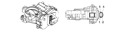
Pin out 1. Earth 2. Fuel supply 3. NC 4. Diagnosis signal 5. NC 6. PWM control (Pulse Width Modulate) |
