





|
|






|
|
Service News
|
|
Copyright By FCA Italy S.p.A. - Printed 20/06/2022
|
|
|
Various models
Version: All models
|
|
|
|
|
5530 B 000 AA
|
BATTERIES
Instructions for correctly checking the battery charge state - Network information
|
|

|
Cancels and replaces SN 55.05.11 of 08/04/2016.
|
The following table gives the available instruments recognized by Stellantis and their use:
|
Mopar Battery Tester |
Charge state check of the following batteries: Lead (Pb) flooded, Pb Heavy Duty, Pb AGM, Pb AGM Spiral |
2000037001 |
Midtronics EXP 813 FCA |
|
Midtronics GRX 3228 FCA |
Integrated instrument for checking the charge state of the following batteries: Lead (Pb) flooded, Pb Heavy Duty, Pb AGM, Pb AGM Spiral |
2000035900 |
Midtronics GR-1 240 |
|
Mopar Universal Battery Charger |
Battery charger |
2000036901 |
CTEK MXS 25000 FCA |
|
ISEAT CB-1 |
|
FCA UNIVERSAL BATTERY CHARGER |
|
CTEK MXS 10 FCA |
APPENDIX 1 contains a description of the instruments and their specifications. For further information, refer to the instruments’ instruction manuals.
Other equipment can only be used to recharge the battery, as an alternative to those listed in the table, on condition that they comply with the minimum requirements given in APPENDIX 2.

|
USING INSTRUMENTS THAT DO NOT MEET THE MINIMUM REQUIREMENTS FOR RECHARGING BATTERIES, DOES NOT ALLOW NOR GUARANTEE RECHARGING THE BATTERY CORRECTLY AND COULD SERIOUSLY DAMAGE THE CAR’S ELECTRICAL/ELECTRONIC COMPONENTS.
|
PRELIMINARY VERIFICATION CONDITIONS
Before connecting the instrument and performing the diagnosis, make sure that the following conditions are met:
On the vehicle:
-
Engine stopped.
-
No electrical devices on, except for permanent key-off loads (e.g. the clock).
-
No recharging system DTC errors in the control units.
On the instrument:
-
Software updated to the latest release (see APPENDICES 3, 4, 5 and 6).
-
Leads, clips and connectors in good condition.
-
The charge level of the buffer battery inside the equipment must be optimal and able to perform the test in the event of a fully discharged vehicle battery.
|
|
The new Mopar Battery Tester (p/n 2000037001) must be connected to the Internet. A Wi-Fi connection to access and configure the instrument in the cloud where the results of the checks are downloaded. This allows the control department to verify the test performed directly in the cloud and the workshop no longer needs to issue a receipt having interventions carried out under warranty recognised.
|
Mopar Battery Tester - Wi-Fi Activation
-
Use the LEFT and RIGHT arrows to select the SETTING function (CROSSED SPANNER AND HAMMER icon) from the main menu.
-
Use the UP and DOWN arrows and select WI-FI.
-
Continue by following the instructions on the display to connect to the wireless network.
For all models in which the battery is easily accessible, check also that:
-
The battery has no external damage.
-
The battery terminals are clean (otherwise, clean them e.g. with a stiff brush).
|
|
No refunds will be granted for operations with test result printouts containing incorrect, incomplete or inaccurate data due to the use of equipment in sub-optimal conditions or failure to comply with the conditions described above.
|
INSTRUMENT POWER SUPPLY
-
Mopar Battery Tester: activates automatically after the correct connection of the clamps.
-
GRX 3228 FCA: connect the equipment to a socket (220 V AC power) and turn the ignition switch to ON.
INSTRUMENT CONNECTION
For all models (except for Fiat Freemont), it is recommended to check the battery charge state by connecting the instrument directly to the battery terminals, leaving it connected to the car’s electrical system.
|
|
At the end of the check procedure, make sure that the clamps are tightened properly to the battery terminals.
|
Use the leads in the kit to connect the instruments as follows:
-
Red clip connected to the positive battery terminal (or to the positive dummy pole).
-
Black clip connected to the negative battery terminal (or to the negative dummy pole).
|
|
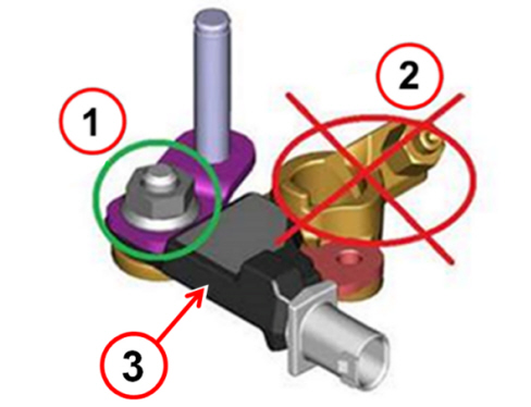
For vehicles equipped with IBS (Intelligent Battery Sensor) (3 - Fig. 1) the connection on the negative pole must be made exclusively on the nut (1) NEVER on the terminal (2).
|
Fig. 1
The lead clips must be connected correctly; an incorrect connection could cause the following messages:
-
On the Mopar Battery Tester - CHECK CLAMP
-
On the GRX 3228 FCA – CHECK TERMINAL CONNECTIONS
If the leads are connected with the wrong polarity, the following message will appear on the display of the GRX 3228 FCA: REVERSED TERMINALS, accompanied by an alarm signal.
Alfa Giulia and Alfa Stelvio
The battery of Alfa Giulia and Alfa Stelvio is in the luggage compartment; refer to the specific procedures of the Technical Assistance Manual to access the terminals.
Fiat Freemont
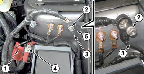
All checks for battery charge status and recharge must be COMPULSORILY made with the battery earth lead (3 - Fig. 2) disconnected from the vehicle negative dummy pole, proceeding as follows:
-
Remove the earth lead fixing nut (2).
-
Disconnect the battery earth lead (3) from the negative dummy pole and reconnect it to the earth pin through the insulating hole (5) and lock it in position with the same nut (2).
-
Open the cover (1) on the dummy positive pole (4).
-
Connect the red clamp to the dummy positive terminal.
-
Connect the black clamp to the dummy negative terminal.
Fig. 2
|
|
At the end of the check procedure:
• Close the cover (1) on the dummy positive pole (4) again.
• Remove the earth lead fixing nut (2).
• Pull the earth lead (3) out of the insulating hole (5), reconnect it to the negative dummy pole and lock it in position with the nut (2), tightening it to a torque of 2.8 daNm.
|
CHECK CHARGE
The following is the procedure for checking the state of charge of the battery using the following tools:
A. Mopar Battery Tester
B. Midtronics GRX 3228 FCA
A. Mopar Battery Tester
|
|
The instruments must be configured correctly, setting the battery rated values and test standards, as given on its label.
|
Vehicles with Start and Stop system
1. In the main menu, use the LEFT and RIGHT arrows to select “BATTERY START / “DIAGNOSIS” (battery icon with letter A on the display).
2. Press Enter to confirm; the request (3) to scan the barcode corresponding to the VIN will appear on the display (1 - Fig. 4) of the instrument (2).
Vehicles WITHOUT Start and Stop system
1. In the main menu, use the LEFT and RIGHT arrows to select “BATTERY TEST” (battery icon on the display).
2. Press Enter to confirm; the request (3) to scan the barcode corresponding to the VIN will appear on the display (1 - Fig. 4) of the instrument (2).
VIN acquisition via scanner (for all vehicles with and without Start and Stop system)
According to whether the barcode corresponds to the VIN is present or absent, follow the instructions in the following paragraphs A or B.
|
|
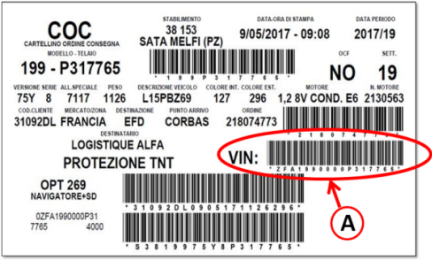
For almost all models, the bar code corresponding to the VIN is shown on the O.D.C. (Order Delivery Certificate) (A- Fig. 3) shows the new cars on a slide glass, prior to delivery to the customer.
|
Fig. 3
A - Vehicles with barcode corresponding to the VIN
-
When the request (3 - Fig. 4) to scan the barcode corresponding to the VIN is displayed, use the UP and DOWN arrows to select YES.
-
Aim the scanner (4 - Fig. 4) on the back of the instrument (2) towards the barcode.
-
Press Enter to acquire the code.
-
After acquiring the barcode; the display (1 - Fig. 4) of the instrument (2) shows the request to specify the type of battery to be checked; continue with step 3 below.
Fig. 4
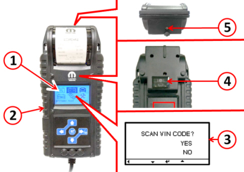
1 - Display
2 - Mopar Battery Tester
3 - VIN acquisition request
4 - Scanner
5 - Temperature sensor
B - Vehicles WITHOUT barcode corresponding to the VIN
-
When the request (3 - Fig. 4) to scan the barcode corresponding to the VIN is displayed, use the UP and DOWN arrows to select NO.
-
Press Enter to confirm. The display (1 - Fig. 4) of the instrument (2) shows the request to specify the type of battery to be checked; continue with step 3 below.
-
After checking the battery, manually enter the VIN as specified in step 14.
Vehicles with Start and Stop system
3. With the UP and DOWN arrows select the battery type
- AGM FLAT PLATE - (Pb AGM)
- EFB – (Enhanced Flooded Battery)
4. Press the Enter button to continue.
Vehicles WITHOUT Start and Stop system
3. With the UP and DOWN arrows select the battery type
- FLOODED (free acid for standard applications)
- AGM FLAT PLATE
- AGM SPIRAL
- VRLA/GEL (normally not used)
4. Press the Enter button to continue.
For all vehicles with and without Start and Stop system
5. After pressing Enter (step 4 for vehicles with and without Start and Stop), the display of the instrument shows the request to specify the type of battery to be checked. Use the UP and DOWN buttons to select the TEST STANDARD (RATING) following the indications given on the battery label, according to the following table:
|
EN |
EN |
|
EN2 |
EN2 |
|
JIS |
JIS |
|
SAE |
SAE |
|
EN - SAE |
EN |
|
EN2 - SAE (with the same current value) |
EN2 |
(*) If both standards are present, select one of the two standards (EN2 or IEC), taking care when entering the corresponding current value (A).
6. Press the Enter button to continue.
7. Use the UP and DOWN arrows to select (or key in) the current value (A) for the test standard according to the battery label.
8. Press the Enter button to continue.
9. Use the UP and DOWN arrows to select whether the battery is on the vehicle (YES or NO).
10. Press the Enter button to continue.
11. If "Battery on vehicle" is selected, use the UP and DOWN arrows to select the connection type: battery terminals (Direct Connect) or dummy terminals (Jump Start Post).
12a. If battery terminals (Direct Connect) was selected, measure the temperature by placing the sensor (5 - Fig. 4) about 2.5 cm from the battery, continue with step 13.
12b. If dummy terminal (Jump Start Post) was selected, use the UP and DOWN arrows to select and confirm the make, model and version of the vehicle being tested, then continue with step 13.
13. Press the Enter key: the instrument starts checking the charge state.
|
|
During the check the instrument may ask if the battery has been recently charged; select Yes or No with the UP and DOWN arrows and press Enter to confirm.
|
At the end of the check, the result is shown on the display of the instrument (Fig. 5).
Take note of the result of the check and, if not previously detected by the scanner, proceed by manually entering the VIN code as described in step 14.
Then, according to the result (1 - Fig. 5), carry out the operations prescribed in the "Check and Repair Result" chapter.
Fig. 5 – Result of the battery check with Mopar Battery Tester
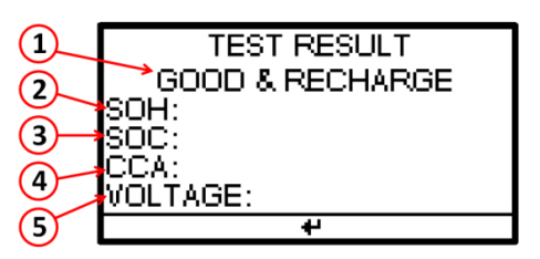
1 – Battery test result
2 – State of Health - SOH
3 – State of Charge - SOC
4 – Cold Cranking Ampere - CCA
5 – Voltage
14. Press Enter: the display of the instrument shows the request to manually enter the VIN code.
Use the UP and DOWN arrows and select:
• YES - in the case of warranty claims and the VIN was not detected with the scanner at the beginning of the procedure - proceed as described in step 15.
• NO - in the case of out-of-warranty service or warranty service and the VIN has already been detected with the scanner at the beginning of the procedure - in the latter case, continue as described in step 16.
15. After selecting YES, a keyboard appears on the display; use the UP - DOWN - LEFT - RIGHT arrows to enter the VIN code.
Make sure the VIN code is correct then select VIN (VIN input) to confirm or select Abort to repeat the VIN entry.
After confirming the VIN (input VIN) continue with the indications shown on the display until the Test Code screen appears - continue as described in step 17.
16. After selecting NO, continue with the indications shown on the display until the Test Code screen appears - continue as described in step 17.
17. The Test Code screen informs you that the result of the test has been automatically sent to the server (cloud) or that, due to lack of connection to the wireless network, the result has been stored.
|
|
When the connection to the wireless network is restored, the instrument will automatically send the stored results to the server.
|
|
|
Set the CCA standard on the instrument if the standard on the battery is different from those listed above.
|
B. Midtronics GRX 3228 FCA
|
|
The instruments must be configured correctly, setting the battery rated values and test standards, as given on its label.
|
In the main menu, use the LEFT and RIGHT arrows to select “BATTERY TEST” / “DIAGNOSIS” (battery icon on the display) and proceed as follows:
1. Use the UP and DOWN arrows to select the TEST LOCATION:
• BATTERY TERMINAL (A)
• STARTER TERMINAL (B)
2. Press the NEXT button to continue.
(A) - If BATTERY TERMINAL was selected, proceed as follows:
1. Select the battery location:
• OUTSIDE THE VEHICLE
• IN THE VEHICLE
2. Press the NEXT button to continue.
3. Select the BATTERY TYPE:
4. Press the NEXT button to continue.
5. Select the NOMINAL UNIT (TEST STANDARD) following the indications given on the battery’s label, according to the following table:
|
EN |
EN |
|
EN2 |
EN2 |
|
JIS |
JIS |
|
EN - SAE |
EN |
|
EN2 - SAE (with the same current value) |
EN2 |
(*) If both standards are present, select one of the two standards (EN2 or IEC), taking care when entering the corresponding current value.
|
|
If the standard on the battery is different from EN, EN2, SAE, JIS, set the CCA standard on the instrument.
|
6. Press the NEXT button to continue.
7. Select the POWER (current) relative to the selected standard as given on the battery’s label.
8. Press the NEXT button to continue.
(A) - If STARTER TERMINAL was selected, proceed as follows:
1. Select the CAR BRAND:
• FIAT
• CHRYSLER
• DODGE
• LANCIA
2. Press the NEXT button to continue.
3. Select the CAR MODEL:
One or more options are available, depending on the previously selected manufacturer.
4. Press the NEXT button to continue.
5. Select the BATTERY VALUE:
It may not be required for some models, if they are equipped with a single type of battery.
6. Press the NEXT button to continue.
The instrument automatically proceeds sequentially to:
• Charge status control
• Charge (if necessary)
• Final check after recharge
While charging, the following parameters are displayed:
• Charging voltage
• Charge current
• Remaining charge time
• Charge amount supplied to the battery in Ah
At the end of the test, the display shows the result (Fig. 6); the screens can be scrolled with the UP and DOWN arrows.
• To print the results, press the PRINT function key.
• To return to the Main menu, press the EXIT function key.
Fig. 6 – Result of the battery check with GRX 3228 FCA
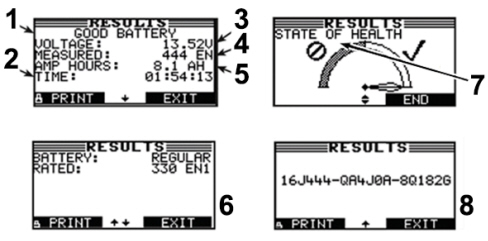
1 – Battery test result
2 - Total charging time
3 – Measured voltage
4 – Measured current
5 – Charging current
6 – Rated battery data
7 – Health status
8 – Test code
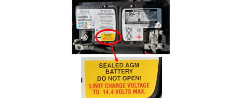
• AGM: If the AGM designation is shown on the battery label. The AGM battery is currently used on RAM and JEEP Wrangler, Cherokee, Grand Cherokee models, with the label type shown in the image.
• NORMAL: for all flooded batteries (STOP&START or non-STOP&START) without the AGM designation on the label.
Flooded battery for S&s Clarios/Varta application (L4, L5, L6)
The label alternatively states: HD (Heavy Duty, previous definition of S&S battery and prescriptions for replacement with similar technology. Midtronics setting: Normal
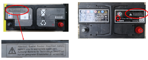
Flooded battery for S&s Exide application (L1, L2, L3)
The label states EFB (Enhanced Flooded BATTERY), a new common definition of S&S battery and prescription for replacement with similar technology. Midtronics setting: Normal
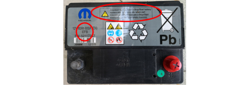
Flooded battery no S&S Exide (L1, L2, L3)
The label does not show HD or EFB or requirements for replacement with similar technology. Midtronics setting: Normal
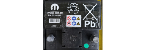
The following options can no longer be used:
• SPIRAL - AGM: this type of battery used only on Freemont; it is not currently used on other vehicles under warranty and no future use is planned
• GEL Pb: never used as a starter battery because it is not technically suitable
CHECK AND REPAIR RESULT
Depending on the test results, perform the operations in the table below:
|
Good battery (Good & Pass) |
Good battery |
No operation. |
|
Good-Recharge (Good & Recharge) |
- |
Completely recharge the battery using the instruments recommended by FCA and then perform the diagnosis again. |
|
Charge and repeat the test (Recharge & Retest) |
- |
Completely recharge the battery using the instruments recommended by FCA and then perform the diagnosis again. |
|
Change battery (Bad & Replace) |
Change battery |
Replace the battery with a new one, referring to the spare parts catalogue for the specific chassis. |
|
Faulty cell (Bad Cell Replace) |
Faulty cell |
Replace the battery with a new one, referring to the spare parts catalogue for the specific chassis. |
|
- |
Battery too hot |
Leave the battery to cool down and then perform the diagnosis again. |
|
- |
Frozen battery |
Leave the battery to thaw and then perform the diagnosis again. |
|
|
If the test results confirm the need to replace the battery, a test MUST be performed on the new battery, to ensure optimal charge conditions.
|
|
|
During Pre-Delivery Inspection (PDI), it is mandatory to recharge the main and auxiliary battery (if present) on all vehicles (even in the case of batteries replaced and/or defined as "good" by the tool)
|
CLAIM FORM DATA
For the battery checks and eventual replacement to be done under warranty, it is mandatory to attach all the result print-outs from the diagnosis equipment to the repair order, as described in this Service News.
For the new Mopar Battery Tester instrument (p/n 2000037001) it is no longer necessary to print and attach the receipt. Make sure that the instrument is connected to the Internet via a Wi-Fi network and that at the end of the verification it has sent the result to the specific site in the cloud.
|
|
Operations performed under warranty will not be refunded if the test results are not printed, even if this is due to an insufficient level of charge of the internal buffer battery of the test equipment in the event of a completely flat vehicle battery.
|
|
|
The presence of non-genuine Mopar system or accessory device (electrical/electronic) not installed according to the technical specifications of the manufacturer will invalidate the warranty of the battery and/or of other concerned systems or components.
|
The result print-outs must contain at least the following data:
-
Date and time
-
Test result
-
Measured voltage
-
Measured amperage
-
Battery rated current and the relative standard
-
Indication of previous performed recharge
-
Location of the battery (in the vehicle, outside the vehicle)
-
Position of the terminals (battery terminals, dummy terminals)
-
Type of battery (normal, AGM, spiral)
This information must be included in the message field in the Claim Form in the form of the test code (see ref.8 - Fig.3 and ref.8 - Fig.4). It is possible that paper copies of the print-outs could be requested during the claim assessment.
If the information is incomplete, incorrect or if there is evidence of failure to apply the procedure described in this Service News, FCA reserves the right not to reimburse the repair costs.
|
Preliminary diagnosis + battery replacement |
5530B10 |
defined by Tempario |
|
For each battery test, following the first one |
0520G20 |
defined by Tempario |
APPENDIX
The attached file contains the following appendices:
-
Appendix 1 – Description and technical specifications of the instruments
-
Appendix 2 – Minimum requirements for battery chargers
-
Appendix 3 – Mopar Universal Battery Charger and CTEK MXS 25000 FCA software upgrade
-
Appendix 4 – Midtronics EXP 813 FCA software upgrade
-
Appendix 5 – Midtronics GRX 3228 FCA software upgrade
-
Appendix 6 – Mopar Battery Tester software upgrade
To open and download the file, select the corresponding icon.
|
|
Cancels and replaces SN 55.05.11 of 26/09/2019.
|
|
