Removing ( Refitting )

- Position the vehicle on the lift.

Op. 5530B54

- Disconnect the negative battery terminal.


Description


Connector


-


BATTERY


See A001

Op. 7055B51

   Op. 5010B12 CLIMATE CONTROL UNIT AIR INTAKE DUCT - R.R.

   Op. 1064B31 WASTEGATE SOLENOID VALVE GUARD - R.R.

   Op. 1064B35 PRESSURIZED AIR SUPPLY PIPE TO WASTE GATE VALVE - R.R.

   Op. 1064B36 PRESSURIZED AIR SUPPLY PIPE TO WASTE GATE ACTUATOR - R.R.

   Op. 1064B44 WASTE GATE VALVE ACTIVATION SOLENOID VALVE - R.R.

   Op. 1064B30 WASTEGATE SOLENOID VALVE MOUNTING BRACKET - R.R.

   Op. 1048A39 SLEEVE FROM AIR CLEANER TO RIGID PIPE - R R

   Op. 1048A38 PIPE BETWEEN AIR FILTER/FLOW METER - R.R.

   Op. 1060G10 AIR FLOW METER - R.R.

   Op. 1048A42 SLEEVE FROM FLOW METER TO TURBO CHARGER AIR INLET PIPE - R + R

   Op. 1016A10 SOUND-PROOFING COVER - R.R

   Op. 1040B28 DUPLEX FUEL SUPPLY/RETURN PIPE TO PRESSURE PUMP - R.R.

   Op. 1060F50 FUEL RETURN MANIFOLD - R.R.

   Op. 1060F53 FLEXIBLE FUEL PIPE FROM PRESSURE PUMP TO RETURN MANIFOLD - R.R.

   Op. 1060F20 PIPE FROM PRESSURE PUMP TO FUEL MANIFOLD - R.R.

   Op. 1008B10 POWER UNIT FRONT SUPPORT FLEXIBLE MOUNTING (TIMING SIDE) - REPLACE

   Op. 1032D12 TIMING SYSTEM PROTECTIVE COVER(S) - R + R


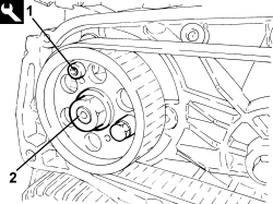
1. Tighten the bolts for the tool to lock the pressure pump pulley to the support.


Tool


Denomination


Function


Validity


2.000.026.900


Kit for removing/refitting pressure pump


Removing/refitting pressure pump


2.0 JTD 115 HP

Rotate the crankshaft until the threaded openings for the pulley are aligned with the corresponding ones for the pressure pump support and fit the calibrated screw in the position shown in the diagram.

2. Undo the pressure pump pulley fixing nut.


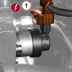
1. Disconnect the electrical connection for the fuel flow rate regulator.


Description


Connector


1


FUEL FLOW REGULATOR


See N193


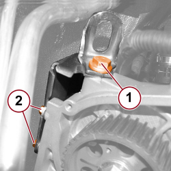
1. Undo the screw and remove the power unit lifting bracket.

2. Undo the bolts and remove the pressure pump guard.


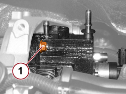
1. Undo the nuts fixing the pressure pump to the mounting.


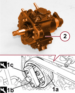
1. Release and remove the pressure pump drive pulley (1a) using the extractor (1b) and the bolts (1c).


Tool


Denomination


Function


Validity


1.860.854.000


Extractor


Pressure pump control pulley removal


2.0 JTD 115 HP


Tool


Denomination


Function


Validity


2.000.026.900


Kit for removing/refitting pressure pump


Removing/refitting pressure pump


2.0 JTD 115 HP

2. Remove the pressure pump.

- Undo the bolts and remove the extractor from the pressure pump pulley.

Mark the position of the pressure pump control shaft centering pin in relation to the pump casing; if it is being replaced, the same operation should be carried out on the new pump obtained from the Parts Dept.


Refitting ( Removing )

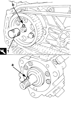
1. Place the pressure pump in position, tighten the tool to rotate the pressure pump shaft so that the centering pin (a) is aligned with the splining (b) on the drive pulley.


Tool


Denomination


Function


Validity


2.000.026.900


Kit for removing/refitting pressure pump


Removing/refitting pressure pump


2.0 JTD 115 HP

- Remove the tool fitted previously for rotating the pressure pump shaft.

- Tighten the nut fixing the drive pulley to the pressure pump to the recommended torque.


Component


Fixing


Ø


Value (daNm)


Validity


Pressure pump drive pulley


Nut


M14


4.5 ÷ 5.5


2.0 JTD 115 HP

- Tighten the nuts securing the pressure pump to the support to the recommended torque.


Component


Fixing


Ø


Value (daNm)


Validity


Pressure pump


Nut


M8


2.3 ÷ 2.8


2.0 JTD 115 HP

- Remove the bolts fixing the drive pulley to the pressure pump support.


Tool


Denomination


Function


Validity


2.000.026.900


Kit for removing/refitting pressure pump


Removing/refitting pressure pump


2.0 JTD 115 HP

- Place the pressure pump protection in its housing and tighten the screws to the prescribed torque.


Component


Fixing


Ø


Value (daNm)


Validity


Injection pump guard


Screw


M6


0.8 ÷ 1.0


2.0 JTD 115 HP

- Place the power unit lifting bracket back in position and tighten the screw to the prescribed torque.


Component


Fixing


Ø


Value (daNm)


Validity


Engine lifting bracket on pump mounting


Screw


M10


4.5 ÷ 5.5


2.0 JTD 115 HP

- Connect the electrical connection for the fuel flow regulator.


Description


Connector


-


FUEL FLOW REGULATOR


See N193

    Op. 1032D12 TIMING SYSTEM PROTECTIVE COVER(S) - R + R

    Op. 1008B10 POWER UNIT FRONT SUPPORT FLEXIBLE MOUNTING (TIMING SIDE) - REPLACE

    Op. 1060F20 PIPE FROM PRESSURE PUMP TO FUEL MANIFOLD - R.R.

    Op. 1060F53 FLEXIBLE FUEL PIPE FROM PRESSURE PUMP TO RETURN MANIFOLD - R.R.

    Op. 1060F50 FUEL RETURN MANIFOLD - R.R.

    Op. 1040B28 DUPLEX FUEL SUPPLY/RETURN PIPE TO PRESSURE PUMP - R.R.

    Op. 1016A10 SOUND-PROOFING COVER - R.R

    Op. 1048A42 SLEEVE FROM FLOW METER TO TURBO CHARGER AIR INLET PIPE - R + R

    Op. 1060G10 AIR FLOW METER - R.R.

    Op. 1048A38 PIPE BETWEEN AIR FILTER/FLOW METER - R.R.

    Op. 1048A39 SLEEVE FROM AIR CLEANER TO RIGID PIPE - R R

    Op. 1064B30 WASTEGATE SOLENOID VALVE MOUNTING BRACKET - R.R.

    Op. 1064B44 WASTE GATE VALVE ACTIVATION SOLENOID VALVE - R.R.

    Op. 1064B36 PRESSURIZED AIR SUPPLY PIPE TO WASTE GATE ACTUATOR - R.R.

    Op. 1064B35 PRESSURIZED AIR SUPPLY PIPE TO WASTE GATE VALVE - R.R.

    Op. 1064B31 WASTEGATE SOLENOID VALVE GUARD - R.R.

    Op. 5010B12 CLIMATE CONTROL UNIT AIR INTAKE DUCT - R.R.

Op. 7055B51

- Connect the negative battery terminal.


Description


Connector


-


BATTERY


See A001

Op. 5530B54

- Remove the vehicle from the lift.