





|
|






|
|
Service News
|
|
Copyright By FCA Italy S.p.A. - Printed 11/02/2016 – Esc.1597
|
|
|
Ducato (250)
Version: All van models with single leaf springs
|
|
|
|
|
4420 1 491 MA
|
REAR SUSPENSION LEAF SPRINGS
Noise/creaking - Service Solution
|
|

|
Cancels and replaces the following Service News:
• SN 44.09.09 of 03/09/2009 for new body bushing replacement procedure.
• SN 44.09.09 of 01/07/2011 for update of bushing assembly tooling
• SN 44.04.11 of 11/11/2011 for the use of new bushings and new washers
• SN 44.04.14 of 09/05/2014 for update of Cycle C.
• 44.04.14 of 10/12/2014 for Part availability table update.
|
CLAIMED FAULT
Creaking coming from the leaf springs.
TECHNICAL CAUSE
Creaking of bushings on rear suspension. The fault occurs on rear bushings only: both on those installed on leaf springs and on those installed on the body.
OPERATIONS IN PRODUCTION
Adoption of new rear bushings on leaf springs (operation 1) and on the body (operation 2), with improved features.
IMPLEMENTATION OF MODIFICATION
Operation 1 - new rear bushings on leaf springs
|
All models in question |
Sevel |
- |
1921275 |
1886543 |
Operation 2 - new rear bushings on body
|
All models in question |
Sevel |
- |
2645205 |
- |
OPERATIONS AT THE DEALERSHIPS
DEALERSHIP BEHAVIOUR STANDARDS TOWARDS THE CUSTOMER
-
Once the customer's claimed fault is confirmed, reassure the Customer that it will be solved by replacing the rear bushings of the rear suspension with new ones, having improved features.
-
After the operation, illustrate what has been done and make sure the Customer is satisfied.
Service Solution
If a creaking sound is heard from rear bushings of rear suspension, depending on the type of chassis and bushing type, carry out the following operation:
-
Vehicles with chassis number before 1921275: on both sides replace the rear bushings on leaf springs (Cycle A or B), the bushings on the body (Cycle C) and the links.
-
Vehicles with chassis number equal or after 1921275 and before 2645205: on both sides replace the rear bushings on body only (Cycle C).
The following Operating Cycle contains the following operations:
-
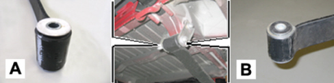
CYCLE A – Replacement of rear bushings on leaf spring with teflon external shim (A - Fig. 1).
-
CYCLE B – Replacement of rear bushings on rubber-metal leaf spring (B - Fig. 1).
-
CYCLE C – Replacement of rear bushings on body.
|
|
The teflon shim (A - Fig. 1) on the vehicle is black; for illustration purposes, Fig. 1 shows a white, unpainted shim.
|
Fig. 1
OPERATION CYCLE
|
|
Two operators are required for this operation.
|
CYCLE A - BUSHINGS WITH TEFLON EXTERNAL SHIM
Equipment required
-
Press (min. 3000 kg)
-
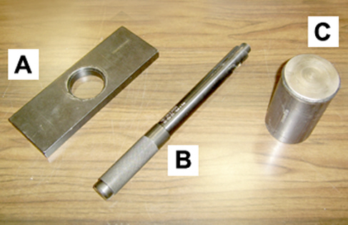
Supporting plate (A - Fig. 2) - (tool no. 200007900)
-
Installer (B) - (tool no. 1870633000)
-
Cylinder for press (C) - (tool no. 187010002)
-
Column hydraulic lift.
Fig. 2
|
|
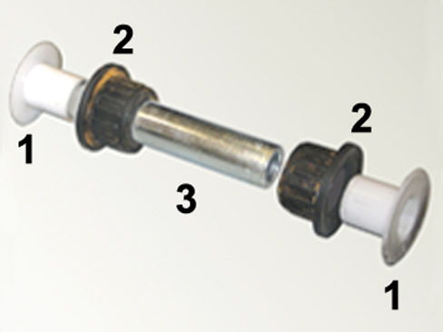
The bushing assembly to be removed is formed by two teflon plates (1 - Fig. 3), two rubber elements (2) and a centre pin (3).
|
Fig. 3
-
Remove the leaf springs from the vehicle, with reference to Op. 4420A60 of the Service Manual.
-
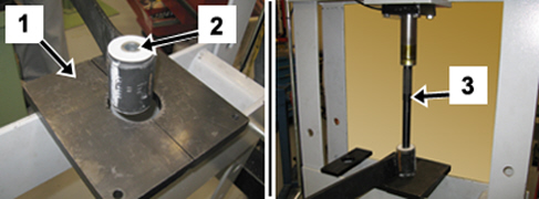
Place the leaf spring on the press, lay it on a plate (1 - Fig. 4) with one centre hole to let the pin (2) come out.
-
Place the installer no. 1870633000 (3) on the pin and, using by the press, make the pin (2) come out from the bushings.
Fig. 4
-
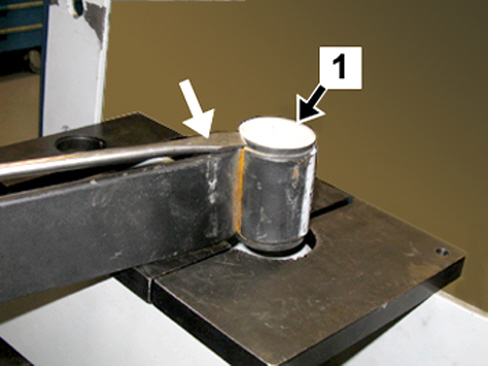
Remove the teflon shim (1 - Fig. 5) from both sides of the bushing, using a screwdriver.
Fig. 5
-
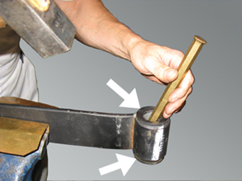
By a punch, make the rubber bushings come out, as shown in Fig. 6, on both sides.
Fig. 6
-
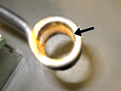
Remove all traces of dirt and oxidation from the bushing housing on the leaf spring, shown in Fig. 7, and lubricate inside for an easier introduction of the new bushings.
Fig. 7
Take the new bushings part no. 1365410080 from the Spare Parts Dpt.
-
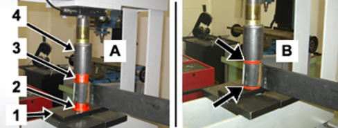
Place the plate part no. 200007900 (1 – Fig. 8) on the press, with the new lower bushing (2) laid on it.
-
Lay the leaf spring on the bushing and locate the upper bushing (3).
-
Place the cylinder part no. 187010002 (4) on the upper bushing, as shown in detail (A) and, using the press, introduce the bushings until their end of stroke, detail (B).
Fig. 8
-
Repeat the same cycle on the leaf spring placed on the opposite side of the vehicle.
-
Refit the leaf springs, with reference to Op. 4420A60 of the Service Manual, securing the front side only, then continue replacing the rear bushings on body (Operation C).
CYCLE B - RUBBER-METAL BUSHINGS
Equipment required
-
Press (min. 3000 kg)
-
Supporting plate (A - Fig. 2) - (tool no. 200007900)
-
Cylinder for press (C – Fig. 2) - (tool no. 187010002)
-
Extractor (tool no. 1840207813)
-
Mallet - (tool no. 1847017001)
-
Column hydraulic lift.
|
|
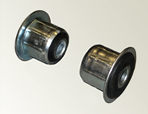
The bushings to be removed are formed by one rubber-metal element each (Fig. 9).
|
Fig. 9
-
Remove the leaf springs from the vehicle, with reference to Op. 4420A60 of the Service Manual.
-
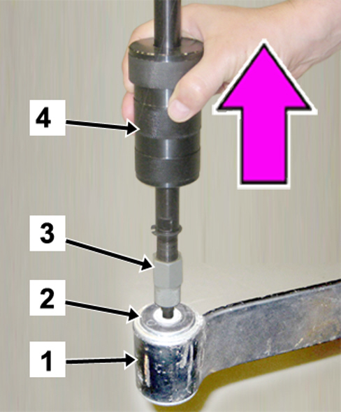
Secure the leaf spring (1 - Fig. 10) in a vice and take out the bushings (2) using an extractor (3) tool no. 1840207813 with a mallet (4) tool no. 1847017001.
Fig. 10
-
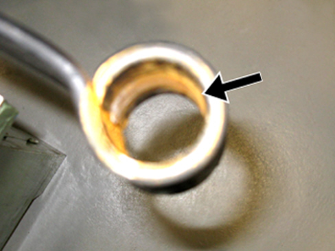
Remove all traces of dirt and oxidation from the bushing housing on the leaf spring, shown in Fig. 11, and lubricate inside for an easier introduction of the new bushings.
Fig. 11
Take the new bushings part no. 1365410080 from the Spare Parts Dpt.
-
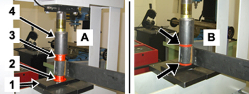
Place the plate part no. 200007900 (1 – Fig. 12) on the press, with the new lower bushing (2) laid on it.
-
Lay the leaf spring on the bushing and locate the upper bushing (3).
-
Place the cylinder part no. 187010002 (4) on the upper bushing, as shown in detail (A) and, by the press, introduce the bushings until their end of stroke, detail (B).
Fig. 12
-
Repeat the same cycle on the leaf spring placed on the opposite side of the vehicle.
-
Refit the leaf springs, with reference to Op. 4420A60 of the Service Manual, securing the front side only, then continue replacing the rear bushings on body (Operation C).
CYCLE C - REAR BUSHINGS ON BODY
Equipment required
-
Installer (B – Fig. 2) - (tool no. 1870633000)
-
Fitting tool - (tool no. 2000025800)
-
Column hydraulic lift.
|
|
The bushing assembly to be removed (A - Fig. 13) is formed by two teflon shims (1), two rubber elements (2) and a centre pin (3).
The assembly of the new bushings to be fitted (B - Fig. 13) is formed by two washers (4) and two bushings, including a spacer (6) replacing the pin (3) that is not used anymore
|
Fig. 13
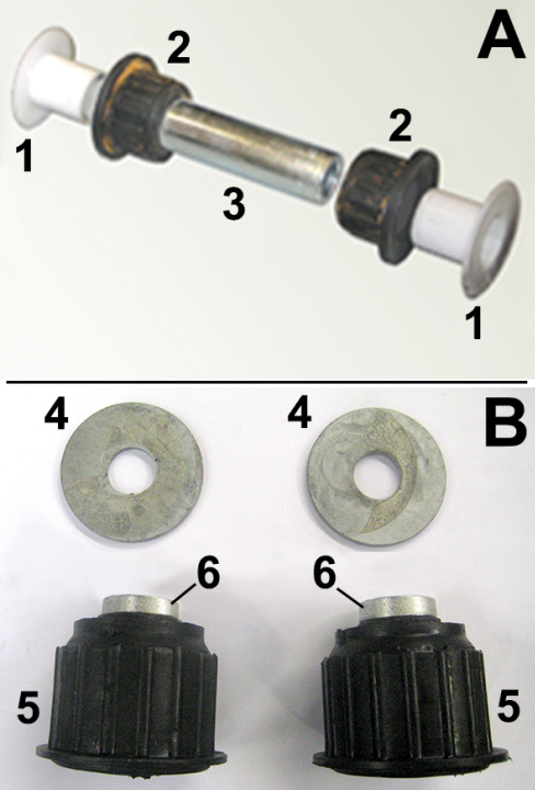
1. Teflon shims
2. Rubber elements
3. Centre pin
4. New washers (part no. 53313502)
5. New bushings (part no. 53313410)
6. Spacer
-
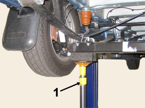
If the previous operation A or B was not performed, remove the links from the vehicle's leaf springs, with reference to Op. 4420A68 of the Service Manual and arrange, in the position corresponding to the leaf spring, a column hydraulic lift (1 - Fig. 14) on the rear axle, to relief the suspension leaf spring.
Fig. 14
-
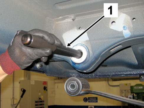
Use the installer no. 1870633000 (1 - Fig. 15) to remove the centre pin.
Fig. 15
-
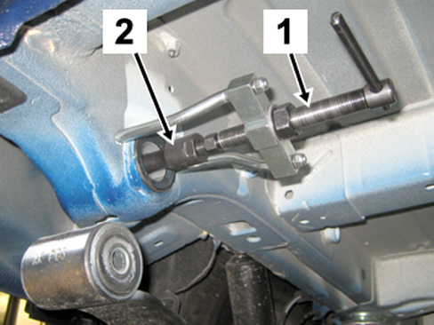
Use an extractor (1 - Fig. 16) (USAG 468D2 or similar) with expansion socket (2) (USAG 468C7 or similar) and remove the internal side bushing.
Fig. 16
-
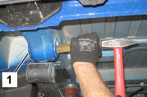
Use a suitably-sized hammer to remove the external side bushing (1 – Fig. 17).
Fig. 17
-
Carefully clean the bushing assembly housing.
-
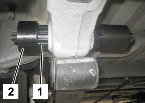
Apply soapy water on the matching surface of the bushings, to facilitate fitting them; then, manually engage the two bushings (1 - Fig. 18). Fully fit the parts until their end of stroke, using the tool no. 2000025800 (2 - Fig. 18).

|
The bushing fitting operation must compulsorily be made with the tool no. 2000025800 (or similar) to be sure that the pressing force is applied on the bushing external metal edge only.
|
Fig. 18
-
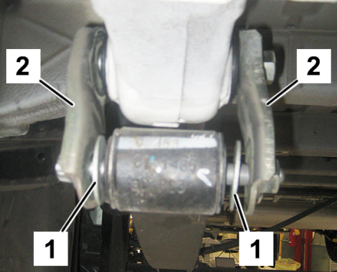
Install the two new washers (1 - Fig. 19) and the two new links (2), then tighten the two fixing bolts to the prescribed torque of 14.5 daNm, with reference to Op. 4420A68 of the Service Manual
Fig. 19
-
Repeat the operation on the opposite side of the vehicle.
-
Check the rear wheel geometry, with reference to Op. 4450A40 of the Service Manual.
PARTS AVALABILITY
|
All models in question |
Rear bushing on leaf spring |
1365410080 |
4 |
|
All models in question |
Rear bushing on body |
53313410 |
4 (*) |
|
All models in question |
Links |
1384062080 |
4 |
|
All models in question |
Washers |
53313502 |
4 (**) |
(*) The pack contains 4 pcs.
(**) The pack contains 10 pcs.
CLAIM REPORT DATA
|
All models in question Cycle A + C or B + C |
4420149 |
1 |
MA |
010-090 |
2.90 (*) |
|
All models in question Cycle C only |
4420150 |
1 |
MA |
010-090 |
1.70 (*) |
(*) Time allowance includes the check of the rear wheel geometry.
|