
|
 Removing
(
Refitting Removing
(
Refitting )
)
- Position the vehicle on the lift. Op. 5530B54 - Disconnect the negative battery terminal.
Op. 7055B51 |
|
|
Op. 1064B35 PRESSURIZED AIR SUPPLY PIPE TO WASTE GATE VALVE - R.R. |
|
Op. 1064B36 PRESSURIZED AIR SUPPLY PIPE TO WASTE GATE ACTUATOR - R.R. |
|
Op. 1064B44 WASTE GATE VALVE ACTIVATION SOLENOID VALVE - R.R. |
|
Op. 1064B30 WASTEGATE SOLENOID VALVE MOUNTING BRACKET - R.R. |
|
|
|
|
Op. 1048A42 SLEEVE FROM FLOW METER TO TURBO CHARGER AIR INLET PIPE - R + R |
|
|
Op. 1040B28 DUPLEX FUEL SUPPLY/RETURN PIPE TO PRESSURE PUMP - R.R. |
|
|
|
|
- If fitted, disconnect the electrical connection for the engine oil sensor signal control unit.
|
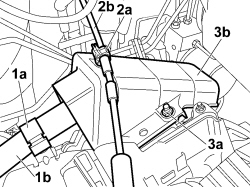 |
1. Release the engine wiring (1b) from the mounting clip (1a). 2. Working on the mounting clip (2a), release the flexible bonnet release cable (2b) and move it away to free the work area. 3. Undo the two fixing nuts (3a) and remove the cover (3b) for the engine management control unit electrical connections. |
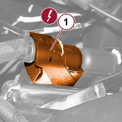 |
1. Undo the safety anchorage, lift the lever and disconnect the engine side electrical connection from the engine management control unit.
|
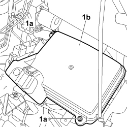 |
1. Undo the fixing nuts (1a) and remove the cover (1b) from the junction unit. |
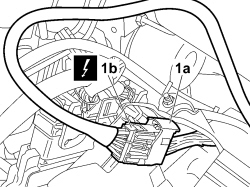 |
1. Adjust the safety lever (1a) and disconnect the electrical coupling (1b) for the engine lead.
- Then release the wiring from the retainers and move it away to free the working area. |
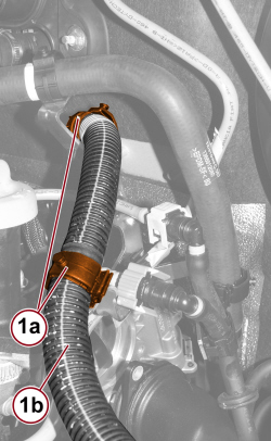 |
1. Open the retaining clips (1a) and release the engine wiring (1b). |
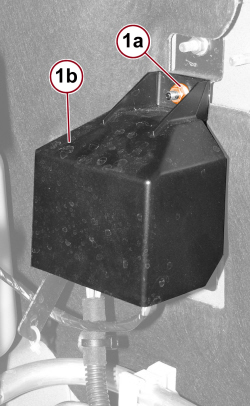 |
1. Undo the nut (1a) and remove the heater plugs control unit cover (2b). |
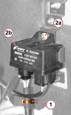 |
1. Release the wiring retaining band. 2. Undo the nut (2a) fixing the heater plugs control unit (2b). |
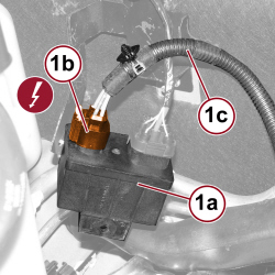 |
1. Turn the control unit (1a) upside down, disconnect the electrical connection (1b) and move the heater plugs wiring (1c) to one side.
|
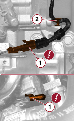 |
1. Disconnect the electrical connection for the air conditioning compressor engagement electromagnet.
2. Open the retaining clip and release the wiring. |
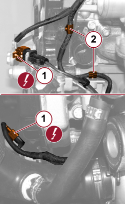 |
1. Detach the electrical connection for the exhaust gas temperature sensor.
2. Open the retaining clips and release the wiring. |
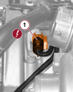 |
1. Detach the timing sensor electrical connection.
|
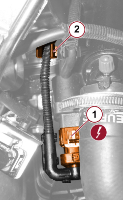 |
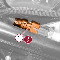
1. Disconnect the electrical connection for the EGR heat exchanger water supply actuator control solenoid.
2. Release the wiring from the clip. |
 |
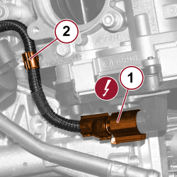
1. Detach the electrical connection for the engine coolant temperature sensor.
|
 |
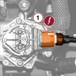
1. Detach the electrical connection for the throttle body.
2. Open the retaining clip and release the wiring. |
 |
1. Disconnect the electrical connection for the EGR solenoid valve.
|
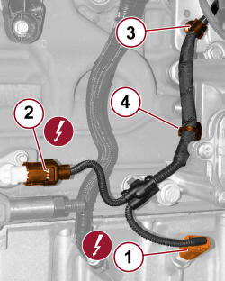 |
1. Detach the engine oil level sensor electrical connection.
2. Detach the rpm sensor electrical connection.
3. Open the retaining clip and release the wiring. 4. Release the wiring retaining band. |
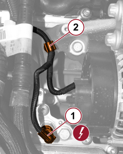 |
1. Disconnect the electrical connection for the engine oil pressure switch.
2. Open the retaining clip and release the wiring. |
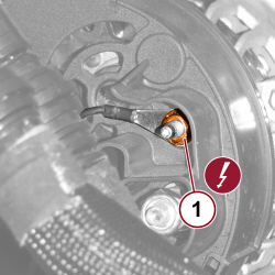 |
1. Undo the nut and disconnect the alternator earth lead.
|
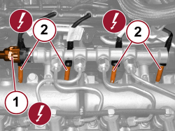 |
1. Detach the fuel pressure sensor electrical connection.
2. Disconnect the heater plug electrical connections.
|
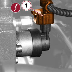 |
1. Disconnect the electrical connection for the fuel pressure regulator.
|
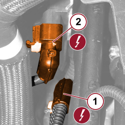 |
1. Disconnect the electrical connection for the air temperature and pressure sensor.
2. Disconnect the electrical connection for the differential pressure sensor upstream and downstream of the particulate filter.
- Release the wiring retaining band. |
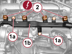 |
1. Undo the screws (1a) fixing the wiring duct (1b) to the camshaft housing. 2. Disconnect the electrical connections for the injectors and move the wiring duct to one side.
|
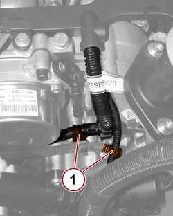 |
1. Release the wiring from the retaining clips. |
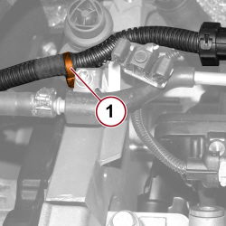 |
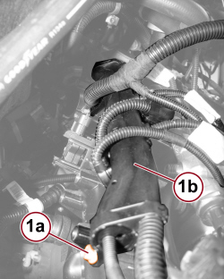
1. Release the wiring retaining band. |
 |
2. Tighten the screws (2a) fixing the wiring duct (2b) to the air chamber. |
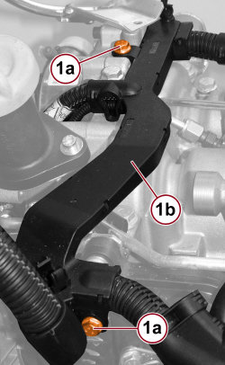 |
1. Undo the camshaft housing and air chamber fixing screws (1a) and remove the wiring duct (1b). |
|
|
Refitting
(
Removing
)
- Place the engine wiring in position and secure it to the retaining clips. - Tighten the screws fixing the wiring duct to the camshaft housing and air chamber. - Fit the wiring retaining band. - Connect the electrical connections for the injectors.
- Tighten the fixing screws securing the injector wiring duct to the camshaft housing. - Connect the electrical connection for the differential pressure sensor upstream and downstream of the particulate filter.
- Connect the electrical connection for the fuel pressure regulator on the pressure pump.
- Connect the electrical connection for the air temperature and pressure sensor.
- Connect the heater plug electrical connections.
- Connect the electrical connection for the fuel pressure sensor.
- Connect the alternator earth lead and tighten the nut.
- Connect the electrical connection for the engine oil pressure switch and engage the wiring with the retaining clip.
- Connect the electrical connection for the rpm sensor.
- Connect the electrical connection for the engine oil level sensor.
- Fit the retaining band and engage the wiring with the retaining clip. - Connect the electrical connection for the EGR solenoid.
- Connect the electrical connection for the throttle body and engage the wiring with the retaining clip.
- Connect the electrical connection for the engine coolant temperature sensor.
- Connect the electrical connection for the water supply actuator control solenoid valve to the EGR heat exchanger and engage the wiring with the retaining clip.
- Connect the electrical connection for the timing sensor.
- Place the harness with exhaust gas temperature sensor in place, tighten the retaining clip and engage the connector in the holding bracket. - Connect the electrical connection for the exhaust gas temperature sensor.
- Connect the electrical connection for the air conditioner compressor engagement electromagnet and engage the wiring with the retaining clip.
- Connect the electrical connection for the heater plugs control unit.
- Tighten the nut fixing the heater plugs control unit. - Engage the wiring retaining band. - Fit the heater plugs control unit cover and tighten the nut. - Secure the wiring to the retaining clips. - Connect the electrical coupling for the engine lead and secure it using the safety lever.
- Place the cover on the junction unit and tighten the fixing nuts. - Connect the engine side electrical connections to the engine management control unit and lock using the safety lever.
- Position the cover on the engine control unit and tighten the nuts. Then secure the wiring to the retaining clip. - Fit the bonnet release cable to the retaining clip. - If fitted, place the engine oil sensor signal control unit in position, tighten the fixing screw and connect the electrical connection.
|
|
|
|
Op. 1040B28 DUPLEX FUEL SUPPLY/RETURN PIPE TO PRESSURE PUMP - R.R. |
|
|
Op. 1048A42 SLEEVE FROM FLOW METER TO TURBO CHARGER AIR INLET PIPE - R + R |
|
|
|
|
Op. 1064B30 WASTEGATE SOLENOID VALVE MOUNTING BRACKET - R.R. |
|
Op. 1064B44 WASTE GATE VALVE ACTIVATION SOLENOID VALVE - R.R. |
|
Op. 1064B36 PRESSURIZED AIR SUPPLY PIPE TO WASTE GATE ACTUATOR - R.R. |
|
Op. 1064B35 PRESSURIZED AIR SUPPLY PIPE TO WASTE GATE VALVE - R.R. |
|
|
|
Op. 7055B51 - Connect the negative battery terminal.
Op. 5530B54 - Remove the vehicle from the lift. |