DESCRIPTION OF COMPONENTSINJECTORSThe injectors are fitted on the cylinder head and controlled by the injection control unit. The injector can be divided into two sections:
Injector operation is divided into three stages. REST POSTION - the coil (4) is de-energised and the plunger (6) is in the closed position to prevent fuel from being introduced into the cylinder Fc > Fa (Fc: due to line pressure acting on control area 7 of rod 1; Fa: due to line pressure acting on feed volume 8). START OF INJECTION, the coil (4) is excited and causes plunger (6) to rise. The control volume fuel (9) flows out towards the return manifold (10) bringing about a pressure drop in the control area (7). Simultaneously, the line pressure flowing through the intake duct (12) exerts a force Fa > Fc in the supply volume (8) causing the pin (2) to lift and allowing fuel into the cylinders. END OF INJECTION - the coil (4) is de-energised and causes the plunger (6) to return to the closed position.This rebalances the forces so that the pin (2) returns to the closed position and the injection ends. Ima classificationDuring inspection the injectors are checked and their specifications under different flow rate/pressure conditions are checked. All the injectors that do not meet a certain standard are rejected; the remaining ones are classified using a 9 character alphanumerical code, known as an IMA code, imprinted by laser on the top part of the magnet. During fitting on the vehicle the control unit should memorise the individual code and, if one or more injectors is replaced in a service situation, the alteration to the code should be made during the diagnosis using the appropriate equipment. 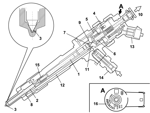
1. Pressure rod 2. Pin 3. Nozzle 4. Coil 5. Pilot valve 6. Ball plunger 7. Control area 8. Feed volume 9. Control volume 10. Fuel return - low pressure 11. Control duct 12. Feed duct 13. Electrical connection 14. Fuel return connector - high pressure 15. Spring 16. IMA code COMMON RAILThe common rail is fitted in the cylinder head on the intake side. With a volume of around 33 cm³, this damps fuel pressure fluctuations due to:
The fuel pressure sensor is fitted at the left end of the supply manifold. The (high pressure) hydraulic connections between the manifold-pump and manifold-injectors are via steel pipes with a bore of 2 mm and an external diameter of 6 mm. |