
 |
 Removing
(
Refitting Removing
(
Refitting )
)
- Position the vehicle on a lift. |
|
- Or |
|
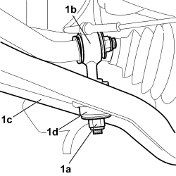
Op. 7055B56 1. Undo the nut (1a) securing the anti-roll bar joint (1b) to the track control arm (1c) from the suspension frame and remove the rubber mounting (1d). |
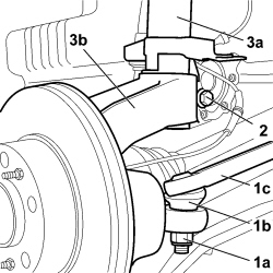 |
1. Undo the fixing nut (1a) and, using the special tool, remove the ball joint (1b) for the steering rod (1c).
2. Undo the bolt fixing the shock absorber to the wheel hub. 3. Release the shock absorber (3a) from the wheel hub (3b). |
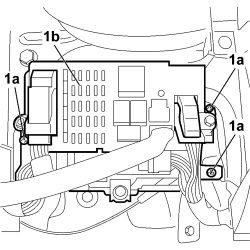 |
- Lower the lift. - Working from inside the vehicle, carry out the following operations: - Left Shock Absorber. Op. 7040A37 Op. 7040A30 1. Undo the fixing bolts (1a) for the body computer mounting bracket (1b) and move it aside to free up the work area. |
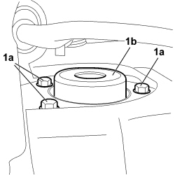 |
1. Undo the bolts (1a) securing the shock absorber (1b) to the turret. |
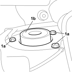 |
- Right Shock Absorber. Op. 7040A18 1. Undo the bolts (1a) securing the shock absorber (1b) to the turret. |
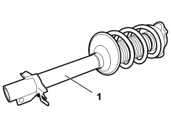 |
1. Remove the shock absorber from the vehicle. |
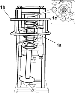 |
1. Position the shock absorber (1a) on the pneumatic spring compression equipment (1b) and, after having compressed the coil spring, release it undoing the fixing nut (1c) using the special tool.
|
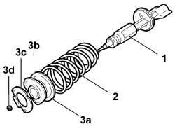 |
1. If there are any faults attributable to the shock absorber, it should be replaced in one piece. 2. Make sure that the coil spring does not show signs of cracks or distortion that could adversely effect its operation. The coil springs are divided into various categories, identifiable by a coloured stripe. Springs with the same colour markings must be fitted. 3. Check the condition of the other shock absorber components: - coil spring cover (3a); - mounting (3b) fixing shock absorber to bodyshell; - seal (3c); - nut (3d) fixing shock absorber to mounting. |
|
|
Refitting
(
Removing
)
- Reassemble the shock absorber using the pneumatic spring compression equipment. - Tighten the nut securing the shock absorber to the mounting to the recommended torque using the special tool.
- Check that the shock absorber assembly is not damaged. - Fit the shock absorber assembly in position. - With the help of the jack, screw in the lower bolt fixing the shock absorber to the wheel hub without tightening it to torque. - Screw in the upper bolts securing the shock absorber to the turret tightening them to the recommended torque.
- Tighten the bolt fixing the lower shock absorber to the wheel hub.
- Right Shock Absorber. Op. 7040A18 - Left Shock Absorber. - Tighten the bolts securing the body computer mounting bracket. Op. 7040A37 Op. 7040A30 - Raise the lift. - Place the steering rod ball joint in position and screw in the fixing nut tightening it to the recommended torque.
- Position the rubber mounting and screw in the nut securing the anti-roll bar joint to the suspension frame track control arm tightening it to the recommended torque.
Op. 7055B56 |
|
- Or |
|
- Remove the vehicle from the lift. Op. 4450A10 FRONT WHEEL GEOMETRY - CHECK USING OPTICAL EQUIPMENT - INCLUDES ADJUSTMENT IF NECESSARY |
|