ARCHITECTURE OF THE ELECTRIC/ELECTRONIC SYSTEM
The electrical system on this vehicle adopts the "Small 2" architecture, developed specifically to integrate the most sophisticated electronic functions in the most efficient way.
This structure is the vehicle's "nervous system": it directly controls all the body functions (access control, visibility, on-board information, comfort etc.) and dialogues with the various chassis and power unit subsystems, optimising dimensions, diagnosticability, reliability, weight and cost of the system.
A further advantage compared with traditional systems is the simplification of assembly through the reduction in the number of control units (with no reduction in the functionality offered to the customer) and the number of power and signal connections, through the extensive use of serial communication networks.
Power is distributed through junction units connected to the control elements (relay switches and static actuators):
-
Body Computer (NBC);
-
Battery Control Unit (CBA);
-
Engine Compartment Junction Unit (CVM);
-
Optional Wiring Control Unit (CCO);
-
Optional Wiring Module (MCA).

|
The relay switches in the Body Computer Node are incorporated into the control unit itself; therefore no type of operation can be carried out (replacement, removal, etc.).
|
The control units also act as an interconnection for the wiring and as an electrical distributor to ensure the maximum level of electrical protection and the minimum degree of wiring complexity.
It is a simplified version of the "MINI F.L.ORE.N.C.E." architecture: the structure has been simplified to manage a greater number of functions with the Body Computer Node.
Network architecture
The "Small 2" architecture consists of 2 CAN communication networks which connect NODES belonging to two different areas:
and a single-wire subnetwork called A-BUS for some automatic alarm functions, Start&Stop, windscreen wiping and exterior lighting.
|
|
All electric/electronic devices containing a specific interface (Network Interface) that permits the transmission and reception of data, information and signals that travel through CANs are called Nodes.
|
The diagnosis connector (EOBD) is external to the Body Computer node and joins the two CAN networks. Therefore, node diagnosis is not performed by means of diagnosis messages sent through the communication networks, except for the Power Steering, Tachograph and Additional (Webasto) Heater control units, which are connected to the diagnosis socket directly.
|
|
An A16HS diagnosis connector is needed in order to be able to converse with the various electronic units.
|
The two C-CAN and B-CAN networks are physically separated but both flow into the BODY COMPUTER NODE; the latter, which is considered the MASTER node for the two networks, is also the GATEWAY which allows the transfer of information/data from one network to another.
The main electronic components managed by the electronic architecture are described in the following diagram:
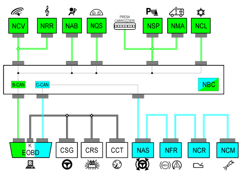
The nodes belonging to the architecture described are located in the vehicle as illustrated in the following figure.
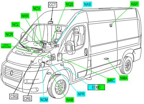
|
NBC |
Body computer node |
M001 |
|
NCM |
Engine management node |
M010 |
|
NQS |
Instrument panel node |
E050 |
|
NRR |
Radio receiver node |
P020 |
|
NSP |
Parking sensor node |
M084 |
|
NAB |
Airbag node |
M060 |
|
NCL |
Climate control node |
M070 |
|
NFR |
Braking System Node |
M051 |
|
CRS |
Additional heater control unit |
M075 |
|
NCV |
Convergence Node (Bluetooth) |
M162 |
|
NAS |
Steering Angle Node |
M092 |
|
NCR |
Robotised Gearbox Node |
M054 |
|
NMA |
Air Springs Node (self-levelling suspension) |
M046 |
|
Bodywork Socket |
Module for Transformers |
P125 |
|
CSG |
Power Steering Control Unit |
M088 |
|
CCT |
Tachograph Control Unit |
E005 |
|
EOBD |
Diagnosis Socket |
R010 |
B-CAN
The B-CAN (highlighted in green in the previous diagram) is the low-speed (50 Kbit/s) serial network responsible for the onboard/body-related functions. It uses two cables (dia. 0.35 mm2), one White/Orange (CAN-B A) and one Black/Orange (CAN-B B). The B-CAN is resistant to network malfunction and adopts the 29-bit standard.
C-CAN
The C-CAN (highlighted in blue in the previous diagram) is the high-speed (500 Kbit/s) serial communication network designed to allow communication among components responsible for the dynamic control of the vehicle. It consists of 2 twisted electric cables (dia. 0.35 mm2), one Blue/Green (CAN-C H), and one Blue/Brown (CAN-C L).
A-Bus serial line
The vehicle's architecture also includes a serial interface connection between different vehicle components and the Body Computer Node.
The ISO 5 serial A-BUS line manages the following components:
|
CSP |
Rain and dusk sensor |
K125 |
|
CSA |
Alarm Siren Control Unit |
P090 |
|
IBS |
Battery Charge Sensor |
K059 |
For further details,
See E1060 A-BUS SERIAL LINE
K lines
In the vehicle's architecture, the K lines that converge directly on the diagnosis connector (EOBD connector) permit diagnosis, using the diagnosis equipment, of the following Nodes / Control Units:
|
CSG |
Power Steering Control Unit |
M088 |
|
CRS |
Additional Heater (Webasto) Control Unit |
M075 |
|
C CT |
Tachograph Control Unit |
E005 |
For further details,
See E8010 DIAGNOSTIC MULTIPLE CONNECTOR
Replacing and initializing network nodes
Some of the CAN nodes are programmed with default settings which the customer will find on purchasing the vehicle.
The nodes storing this information are:

|
If the Body Computer is being replaced, an "identical copy" of the Body Computer must be obtained from the Parts Dept as a V.O.R. order supplying the vehicle chassis number: this copy will contain all the default settings entered on a new vehicle, which are stored in the Spare Parts database for the vehicle chassis number.
|
|
|
If the other nodes described above are being replaced, Spare Parts will send a blank component: once fitted, the initial default data must be transferred to it by carrying out the PROXY ALIGNMENT procedure using Examiner.
|
|
|
If other nodes are being replaced, no initialization operation is required. However, always check that the system has not picked up errors during the removing-refitting operations, etc. using the Examiner.
|
Battery disconnection
If the battery is disconnected, the Body Computer, the Instrument Panel Node and the Airbag Node will keep the information received and do not have to be initialised. The other nodes lose some or all of the stored information and must be initialised.
Logistic mode
There is software inside the Body Computer that excludes all the vehicle's electrical loads, except the main functions (vehicle starting, lights). This function makes it possible to save battery energy which is useful when the vehicle is parked, possibly for long periods, in compounds before being sold.
|
|
The function must be disabled in the workshop before the vehicle is handed over to the customer.
|
Deactivation procedure
The procedure is as follows:
-
Connect the terminal of the diagnosis device to the vehicle's EOBD socket and turn the key to MAR-ON;
-
check that the "alternator recharging" warning light is flashing, to indicate that the low consumption "Logistic Mode" is active;
-
deactivate the low consumption supply mode by carrying out diagnosis of the Body Computer using Examiner;
-
the Body Computer and all control units involved in performing this operation, on receiving the CAN message, will restore their full operation and send a confirmation message to the Body Computer node;
-
delete the error memory in all control units with a diagnosis function;
-
switch off and then on again (keyOFF - keyON);
-
check that the "alternator recharging" warning light is on constantly.
BODY COMPUTER NODE
The Body Computer Node (NBC) is an electronic component which manages the vehicle's serial networks and the basic functions of the vehicle (interior and exterior lighting, diagnosis, windscreen wipers, heated rear window, locking/unlocking of doors, fuel level, management and acquisition of ignition key status etc.)
It houses the communication gateway between the B-CAN and C-CAN and also carries out interconnection functions between cab, front and dashboard wiring.
It is located under the dashboard to the left.
Functions managed by the body computer node
The NBC carries out the following functions:
-
receives and transmits information on the B-CAN (e.g. diagnosis, warning lights, controls, data);
-
receives and transmits information on the C-CAN;
-
houses the gateway for communication between the B-CAN and C-CAN;
-
is connected to the cab, front and dashboard wiring, managing numerous functions;
-
manages low consumption supply mode (Logistic Mode);
-
is connected to the Battery Control Unit (CBA), Engine Compartment Junction Unit (CVM), Optional Wiring Control Unit (CCO) and Optional Wiring Module (MCA) to receive supplies / signals and control relay switches.
The following functions are included:
-
master for the whole system: management of slave nodes in its direct jurisdiction and monitoring by other master nodes, monitoring and management of protocol errors, timer control;
-
diagnosis of the whole system: collection of diagnosis information, management of diagnosis through EXAMINER;
-
immobilizer: management of key code with possible engine ignition release;
-
anti-theft: remote control receiver management and connection with alarm siren system;
-
acquisition of on/off signals: reverse gear engaged, brake lights control, INT from ignition switch, (left) front brake pad wear, bonnet button, door opening status switches, driver and passenger side catch signal, FIS (inertia switch) control, handbrake control, hazard warning lights control;
-
acquisition of analogue signals: parking lights control, engine coolant level, brake fluid level, alternator voltage (D+), outside temperature signal, fuel level, battery voltage, windscreen wiper intermittent operation, light selector from DEV (steering column stalk), main beam headlights/flasher signal from DEV, direction indicators control from DEV, vehicle door locking/unlocking from PCC (Central Control Panel), windscreen wiper selector signal from DEV, windscreen washer selector signal from DEV, headlight alignment adjustment signal from PCS (Left Control Panel), heated rear window control from PCC, rear fog lights control from PCC, fog lights relay control;
-
acquisition and repetition of vehicle speed signal;
-
management of the courtesy lights with timer and dimmer function;
-
management of ON/OFF outputs on relay: windscreen washer pump, headlight washer pump, fog lights, dipped headlights, main beam headlights, starting, windscreen wiper (first and second speeds), services 2 relay;
-
ON/OFF management of one relay during left/right direction indicators or hazard warning lights for acoustic feedback;
-
ON/OFF output management directly on loads and light check function: front (left and right) and rear (left and right) side lights, front (left and right), rear (left and right) and side (left and right) direction indicators, number plate lights (left and right), brake lights (left and right), rear fog lights (left and right);
-
management of the driver for the ideogram lights;
-
management of the driver for SBMT;
-
management of serial line (A-BUS) for: rain/dusk sensor and alarm siren control unit;
-
preparation for possible inclusion of new electrical functions.
Body computer connections
The following image shows the location of the rear connectors of the Body Computer Node.
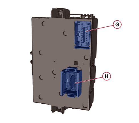
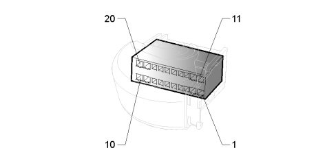
M001G connector PIN-OUT (Grey, 20 pin, dashboard wiring)
|
1 |
Body Computer Node earth |
|
2 |
Active digital signal to Vbatt INT from ignition switch |
|
3 |
INT power supply (F50) for Airbag Node (NAB) |
|
4 |
+30 power supply (F53) for Instrument Panel Node (NQS) |
|
5 |
Setup for power supply +30 (F53) |
|
6 |
SBMT supply setup from contact output Relay T44 (F32) |
|
7 |
INT supply (F51) for tachograph |
|
8 |
INT supply (F51) for infotelematic accessory junction setup |
|
9 |
Active digital signal to Vbatt INT/A from ignition switch |
|
10 |
+30 supply (F36) for Radio Receiver Node (NRR) / Convergence Node (NCV) |
|
11 |
Body Computer Node earth |
|
12 |
INT supply (F49) for driver side control panel / steering wheel control switches |
|
13 |
Provision for power supply INT (F51) |
|
14 |
Setup for power supply INT (F49) |
|
15 |
INT supply (F49) for Radio Receiver Node (NRR) / Convergence Node (NCV) |
|
16 |
Setup for power supply INT (F49) |
|
17 |
INT supply (F37) for Instrument Panel Node (NQS) |
|
18 |
+30 supply (F36) for diagnosis connector (EOBD) |
|
19 |
+30 supply (F36) for tachograph |
|
20 |
Provision for power supply +30 (F36) |
M001H connector PIN-OUT (Grey, 60 pin, dashboard wiring)
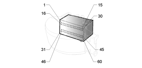
|
1 |
Active analogue input to earth. Negative signal for vehicle Locking/Unlocking |
|
2 |
Active analogue input to earth (5 V reference). Negative Resume/Up/Down signal from steering column stalk - Setup |
|
3 |
Low Side Relay Driver. Driver for Side Marker relay; negative relay coil control |
|
4 |
Low Side Relay Driver. Repetition of D+ alternator negative recharging signal for transformer socket |
|
5 |
Free |
|
6 |
Low Side Driver. Negative Dynamic LED control - Setup |
|
7 |
High Side Driver. Positive control for heated rear screen LED |
|
8 |
High Side Driver. Positive hazard warning lights on LED control |
|
9 |
CAN-B A for diagnosis connector (EOBD) |
|
10 |
CAN-B A for Radio Receiver Node (NRR) |
|
11 |
CAN-B A for Instrument Panel Node (NQS) |
|
12 |
CAN-B A for Airbag Node (NAB) |
|
13 |
CAN-C H for Convergence Node (NCV) - Setup |
|
14 |
CAN-C L for Convergence Node (NCV) - Setup |
|
15 |
Specific signal input from aerial for Code device (immobilizer signal) |
|
16 |
Active analogue input to earth. Negative luggage compartment opening button signal - Setup |
|
17 |
Active analogue input to Vbatt/earth. Active signal from economy button to earth - Setup |
|
18 |
Active analogue input to Vbatt/earth. Driver side electric window lowering control - Setup |
|
19 |
Active analogue input to earth. Negative "Teg Reader" Locked / Unlocked signal - Setup |
|
20 |
Active analogue input to earth (5 V reference). Windscreen wiper intermittent operation negative signal from steering column stalk |
|
21 |
Active analogue input to earth - Free. |
|
22 |
Active analogue input to earth. Negative "Teg Reader" on signal - Setup |
|
23 |
High Side Driver. Positive door status / deterrent LED control |
|
24 |
CAN-B B for diagnosis connector (EOBD) |
|
25 |
CAN-B B for Radio Receiver Node (NRR) |
|
26 |
CAN-B B for Instrument Panel Node (NQS) |
|
27 |
CAN-B B for Airbag Node (NAB) |
|
28 |
CAN-C H for diagnosis connector (EOBD) |
|
29 |
CAN-C L for diagnosis connector (EOBD) |
|
30 |
Specific signal input from aerial for Code device (immobilizer signal) |
|
31 |
Active analogue input to Vbatt/earth. Driver side electric window raising control - Setup |
|
32 |
Low Side Relay Driver. Negative control for interior light relay (T25) of the optional wiring control unit (CCO) |
|
33 |
Speed signal input from tachograph |
|
34 |
Active analogue input to earth. Negative Start&Stop system enablement signal |
|
35 |
Active analogue input to earth. Negative signal from heated rear window button |
|
36 |
Earth reference for driver side control panel |
|
37 |
Earth reference for CRUISE CONTROL |
|
38 |
Active analogue input to earth (5 V reference). Negative signal for LH side steering wheel controls |
|
39 |
Active analogue input to earth. Negative rear fog light / fog light signal from switch control unit |
|
40 |
Active analogue input to earth (5 V reference). Negative rear window wiper signal from steering column stalk - Setup |
|
41 |
Active analogue input to earth (5 V reference). Negative signal from vehicle dynamic selector - Setup |
|
42 |
Active analogue input to earth (5 V reference). Negative lights selector signal from steering column stalk |
|
43 |
Active analogue input to earth (5 V reference). Negative main beam / flasher signal from steering column stalk |
|
44 |
A-bus serial line setup |
|
45 |
Reference earth for steering column switch unit |
|
46 |
Positive signal for Instrument Panel Node (NQS) and left headlight alignment control |
|
47 |
Active analogue input to Vbatt/earth. DCDC converter diagnosis signal |
|
48 |
Active analogue input to Vbatt/earth. Driver side electric window lowering control - Setup |
|
49 |
Positive position control for headlight alignment control from Instrument Panel Node (NQS) |
|
50 |
High Side Driver. Positive fixed lighting control interlocked with side lights |
|
51 |
Active analogue input to earth (5 V reference). Negative signal for RH side steering wheel controls |
|
52 |
High Side Driver. Positive control for Start&Stop system activation LED |
|
53 |
Earth reference for steering wheel controls |
|
54 |
Active analogue input to earth (5 V reference). Negative windscreen washer signal from steering column stalk |
|
55 |
Active analogue input to earth. Negative signal from hazard warning lights switch |
|
56 |
Active analogue input to earth (5 V reference). Negative signal for Cruise Control/Speed Limiter/Off from steering column stalk |
|
57 |
Active analogue input to earth (5 V reference). Negative direction indicator signal from steering column stalk |
|
58 |
Active analogue earth input (5 V reference). Negative windscreen wiper selector signal from steering column stalk |
|
59 |
LIN4 serial line setup |
|
60 |
High Side Driver. Positive control for LED on economy button - Setup |
The following image shows the location of the front connectors of the Body Computer Node.
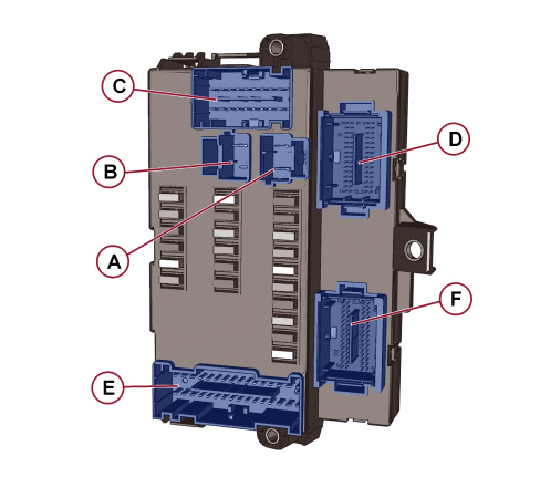
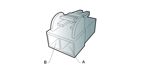
M001A connector PIN-OUT (Grey, 2 pin, cab wiring)
|
A |
+30 supply from F71 from the Battery Control Unit (CBA) |
|
B |
+30 supply from F72 from the Battery Control Unit (CBA) |
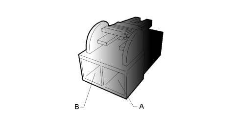
M001B connector PIN-OUT (Black, 2 pin, cab wiring)
|
A |
+30 supply for Optional Wiring Control (CCO) |
|
B |
Free |
M001C connector PIN-OUT (Black, 20 pin, front)
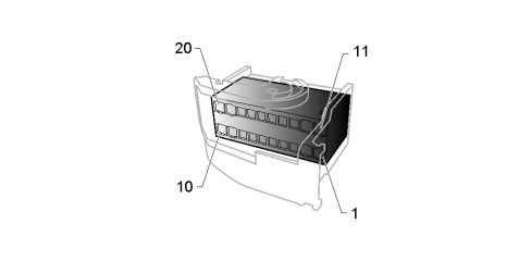
|
1 |
Relay contact output (T01b). Supply from F12 for right dipped headlight |
|
2 |
Relay contact output (T23a). Supply from F43 for windscreen washer |
|
3 |
Relay contact output (T11a). Supply from F90 for left main beam headlight |
|
4 |
INT supply from F51 for clutch pedal switch (normally open) / fuel temperature and water in fuel filter sensor |
|
5 |
Relay contact output (T11b). Supply from F91 for right main beam headlight |
|
6 |
Relay contact output (T12a). Supply from F92 for left fog light |
|
7 |
Supply from F51 for reversing switch |
|
8 |
Relay contact output (T12b). Supply from F93 for right fog light |
|
9 |
Relay contact output (T15b-NC) 1st speed windscreen wiper - Setup |
|
10 |
Relay contact output (T15b-NA) 2nd speed windscreen wiper - Setup |
|
11 |
Relay contact output (T23b). Supply from F43 for rear window washer - Setup |
|
12 |
Relay contact output (T01a). Supply from F13 for left dipped headlight / Headlight alignment control |
|
13 |
+30 supply from F36 for Climate Control Node (NCL) / Additional Heater Control Unit Timer (CRS) / TUM control unit |
|
14 |
+30 supply from F36 for Alarm Siren Control Unit (CSA) |
|
15 |
INT supply from F37 for brake pedal switch (normally closed) |
|
16 |
INT supply from F37 for brake pedal switch (normally open) / TUM control unit |
|
17 |
INT supply from F51 for diesel filter |
|
18 |
INT supply from F51 for air conditioning controls / passenger compartment air fan relay switch |
|
19 |
Active digital input to Vbatt. INT supply from ignition switch - Setup |
|
20 |
INT/A supply from F31 for the coils: T08 (climate control unit relay), T21 (headlight washer relay) and T17 (rear power socket relay) |
M001D connector PIN-OUT (Black, 60 pin, front)
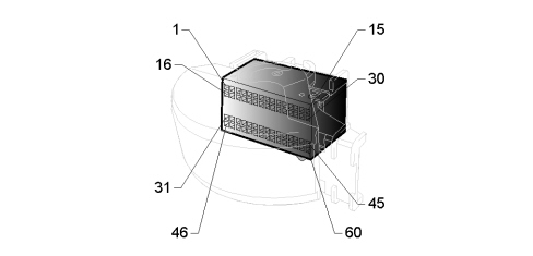
|
1 |
High Side Driver. Positive control for front right side light (COM1 for LED control unit) - Setup |
|
2 |
Active analogue input to earth - Free. |
|
3 |
Driver High Side and active digital input to Vbatt. Positive wake-up control for Braking System Node (NFR) - Setup |
|
4 |
Low Side Relay Driver. Windscreen wiper 2nd speed relay coil negative control |
|
5 |
Low Side Relay Driver. Negative key discharge relay coil control |
|
6 |
High Side Driver. Positive hazard warning lights on LED control - Setup |
|
7 |
Low Side Driver. Driver side door open signal repetition output for Robotised Gearbox Node (NCR) |
|
8 |
Active analogue input to earth. Negative signal from bonnet open indication switch (normally closed) |
|
9 |
Active digital input to earth. Negative hazard warning light switch signal - Setup |
|
10 |
Low Side Relay Driver. Windscreen wiper 1st speed relay coil negative control |
|
11 |
Active digital input to Vbatt. Positive brake pedal switch signal (normally closed) |
|
12 |
INT supply from F42 for Braking System Node (NFR) |
|
13 |
INT supply from F42 for Steering Angle Node (NAS) |
|
14 |
Supply for right headlight alignment control |
|
15 |
High Side Driver. Supply for left headlight day light (DRL) |
|
16 |
Free |
|
17 |
Active analogue input to earth. Negative signal from FIS inertia switch (normally open) - Setup |
|
18 |
Active analogue input to earth. Negative signal from brake fluid level switch |
|
19 |
Low Side Relay Driver. Heated rear window relay coil negative control |
|
20 |
LIN 4 serial line setup |
|
21 |
High Side Driver. Positive control for heated rear window LED -Setup |
|
22 |
Low Side Relay Driver. Headlamp washer relay coil negative control |
|
23 |
Active analogue input to earth. Negative signal from brake pad wear sensor |
|
24 |
Active analogue input to earth. Negative signal from heated rear window button - Setup |
|
25 |
Active digital input to Vbatt/earth (uncoupling diode). Negative signal from FIS inertia switch (normally open) |
|
26 |
A-bus serial line setup |
|
27 |
LIN 3 serial line setup |
|
28 |
INT supply from F42 for brake pedal switch (normally open) |
|
29 |
Supply for left headlight alignment control |
|
30 |
High Side Driver. Supply for right headlight day light (DRL) |
|
31 |
High Side Driver. Front left positive direction indicator control |
|
32 |
High Side Driver. Side left positive direction indicator control |
|
33 |
High Side Driver. Positive control for front left side light (COM2 for LED control unit) - Setup |
|
34 |
Active analogue input to earth - Free. |
|
35 |
Active digital input to earth. Diagnosis feedback from right active headlight to earth (LED) - Setup |
|
36 |
Active digital input to earth. Diagnosis feedback from left active headlight to earth (LED) - Setup |
|
37 |
C-CAN L for Steering Angle Node (NAS) / TUM control unit |
|
38 |
C-CAN H for Steering Angle Node (NAS) / TUM control unit |
|
39 |
Earth for TUM control unit |
|
40 |
CAN-B B for Climate Control Node (NCL) |
|
41 |
CAN-B A for Climate Control Node (NCL) |
|
42 |
Active analogue input to Vbatt/earth. Positive signal for compressor engagement (A/C) |
|
43 |
Active analogue input to Vbatt/earth. Negative engine coolant level signal (normally open) |
|
44 |
Frequency input. Signal from tachograph |
|
45 |
Active analogue input to Vbatt. Positive D+ signal from alternator - Setup |
|
46 |
High Side Driver. Front right positive direction indicator control |
|
47 |
High Side Driver. Side right positive direction indicator control |
|
48 |
High Side Driver. Positive fixed lighting control interlocked with side lights for Climate Control Node (NCL) |
|
49 |
Low Side Relay Driver. Negative starting relay enablement control |
|
50 |
A-bus serial line for Alarm Siren Control Unit (CSA) |
|
51 |
Low Side Driver. Negative All Weather LED control |
|
52 |
CAN-C L - Setup |
|
53 |
CAN-C H - Setup |
|
54 |
High Side Driver. Positive right headlight side light control |
|
55 |
High Side Driver. Positive left headlight side light control |
|
56 |
Low Side Driver. Speed signal generation VSO / B7 |
|
57 |
Active digital input to Vbatt. Positive brake pedal switch signal (normally open) |
|
58 |
Negative signal from windscreen wiper cam |
|
59 |
Positive position control for left headlight alignment control from Instrument Panel Node (NQS) |
|
60 |
Positive position control for right headlight alignment control from Instrument Panel Node (NQS) |
M001E connector PIN-OUT (Black, 32 pin, Cab)
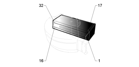
|
1 |
Relay contact output (T25a). Supply from F47 for driver side electric window raising control |
|
2 |
Relay contact output (T25b). Supply from F47 for driver side electric window lowering control |
|
3 |
Relay contact output (T37c). Supply from F38 for central door locking control (Dead Lock) |
|
4 |
+30 supply from F36 for Battery Disconnecting Control Unit (BDS) |
|
5 |
INT supply from F49 - Setup |
|
6 |
INT supply from F49 for transformer socket |
|
7 |
INT supply from F49 for rain and dusk sensor |
|
8 |
Relay contact output (T38a). Supply from F89 for folding mirrors - Setup |
|
9 |
Relay contact output (T38b). Supply from F89 for opening rear window release - Setup |
|
10 |
INT supply from F49 for Battery Disconnecting Control Unit (BDS) |
|
11 |
INT supply from F51 - Setup |
|
12 |
INT supply from F51 - Setup |
|
13 |
INT supply from F51 - Setup |
|
14 |
Relay contact output (T37d). Supply from F38 for load compartment/rear sliding side door locking |
|
15 |
Relay contact output (T26b). Supply from F48 for passenger side electric window lowering control |
|
16 |
+30 supply from F47 for driver side electric window |
|
17 |
+30 supply from F34 for interior hazard warning lights (Minibus) |
|
18 |
Relay contact output (T37a). Supply from F38 for front door locking |
|
19 |
+30 supply from F33 for battery monitoring system |
|
20 |
High/Low Side Driver. Positive rear window wiper motor control - Setup |
|
21 |
Supply from F36 for Optional Wiring Control Unit (CCO) and Optional Wiring Module (MCO) |
|
22 |
Relay contact output (T44). SBMT supply from F32 for front roof light |
|
23 |
Relay contact output (T44). SBMT supply from F32 for luggage compartment roof light |
|
24 |
Relay contact output (T44). SBMT supply from F32 for access board light |
|
25 |
Relay contact output (T44). SBMT supply from F32 |
|
26 |
Earth reference for rear bulbs - Setup |
|
27 |
INT/A supply from F31 for Multifunction screen node / Battery Disconnecting Control Unit (BDS) / Relay (T66) for Optional Wiring Control Unit CCO |
|
28 |
Relay contact output (T44). SBMT supply from F32 |
|
29 |
Relay contact output (T44). SBMT supply from F32 |
|
30 |
Relay contact output (T26a). Supply from F48 for passenger side electric window raising control |
|
31 |
+30 supply from F48 for passenger side electric window |
|
32 |
Relay contact output (T37b). Supply from F38, for front door unlocking / Shared with central door locking (deadlock) |
M001F connector PIN-OUT (green, 60 pin, Cab)
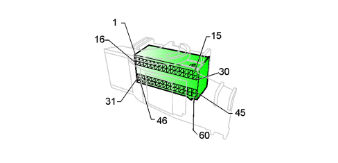
|
1 |
High Side Driver. Positive right reversing light control / Multifunction screen node |
|
2 |
High Side Driver. Positive left brake light control |
|
3 |
High Side Driver. Positive rear right fog light control |
|
4 |
High Side Driver. Positive left reversing light control |
|
5 |
High Side Driver. Positive electric window enablement control |
|
6 |
High Side Driver. Positive left and right number plate light control |
|
7 |
High Side Driver. Positive fixed lighting control interlocked with side lights for Multifunction screen node |
|
8 |
Low Side Driver. Front roof light timer/dimmer negative control |
|
9 |
Active analogue input to Vbatt. Rear left roof light positive signal - Setup |
|
10 |
Low Side Driver. Rear second row roof light dimmed/timed negative control |
|
11 |
Active analogue input to Vbatt/earth. Negative trailer presence signal (normally open) - Setup |
|
12 |
Active analogue input to earth. Diagnosis feedback from right active headlight to earth (LED) - Setup |
|
13 |
Low Side Driver. Rear first row roof light dimmed/timed negative control |
|
14 |
A-bus serial line for rain and dusk sensor - Setup |
|
15 |
RF aerial coaxial cable input signal |
|
16 |
High Side Driver. Free for exterior lights 2 |
|
17 |
High Side Driver. Positive right front and rear side light control |
|
18 |
High Side Driver. Positive rear right direction indicator control |
|
19 |
High Side Driver. Positive rear left direction indicator control |
|
20 |
Active analogue input to Vbatt/earth. Positive driver side electric window lowering control - Setup |
|
21 |
Low Side Relay Driver. Second external heated rear window relay driver |
|
22 |
Active analogue input to Vbatt. Rear right roof light positive signal - Setup |
|
23 |
Active analogue input to Vbatt. Positive front roof light signal - Setup |
|
24 |
Negative fuel level signal from tank |
|
25 |
Positive fuel level signal from tank |
|
26 |
Active digital input to earth. Negative digital rear window wiper cam signal - Setup |
|
27 |
Active analogue input to earth. Negative load compartment locking/unlocking signal from Control Panel on door |
|
28 |
A-bus serial line setup |
|
29 |
Low Side Driver. Negative electric window/Sun Roof enablement signal (comfort closing) - Setup |
|
30 |
Earth reference for RF aerial |
|
31 |
High Side Driver. Positive rear left fog light control |
|
32 |
High Side Driver. Positive right brake light control |
|
33 |
Active analogue input to earth. Negative signal from switch on rear right sliding side door (normally open) |
|
34 |
Active analogue input to earth. Negative signal from opening switch on tailgate handle - Setup |
|
35 |
Active analogue input to earth. Negative signal from switch on tailgate (normally open) |
|
36 |
Active analogue input to earth. Negative signal from switch on rear left sliding side door (normally open) |
|
37 |
Specific input for outside temperature signal |
|
38 |
Active analogue input to earth. Negative signal from switch on rear window - Setup |
|
39 |
LIN 3 serial line setup |
|
40 |
Active analogue input to Vbatt/earth. Positive signal for passenger side electric window raising/lowering control |
|
41 |
High Side Driver. Positive load compartment door status LED control |
|
42 |
Active analogue input to earth. Diagnosis feedback from left active headlight to earth (LED) - Setup |
|
43 |
Active analogue input to earth. Negative emergency button input for minibus |
|
44 |
Active analogue input to earth. Negative signal from handbrake engaged indication switch (normally open) |
|
45 |
CAN-B A for Parking Sensor Node (NSP) |
|
46 |
High Side Driver. Free for exterior lights 1 |
|
47 |
High Side Driver. Positive left front and rear side light control |
|
48 |
High Side Driver. Positive third brake light control |
|
49 |
Low Side Driver. Speed signal generation VSO / B7 |
|
50 |
Active analogue input to earth. Negative signal from switch on driver side front door |
|
51 |
Active analogue input to earth. Negative signal from switch on passenger side front door |
|
52 |
Earth reference for outside temperature sensor |
|
53 |
Active analogue input to Vbatt/earth. Analogue driver side front door geared motor pawl signal |
|
54 |
Active analogue input to Vbatt/earth. Positive passenger side electric window raising/lowering control signal from driver side dashboard |
|
55 |
Active analogue input to Vbatt/earth. Positive driver side electric window raising/lowering control signal from driver side dashboard |
|
56 |
Active analogue input to Vbatt/earth. Negative passenger side front door geared motor pawl signal / Mirror folding signal - Setup |
|
57 |
Low Side Driver. Negative and timed step light control |
|
58 |
Low Side Driver. Negative and timed load compartment roof light control / removable roof light |
|
59 |
Active digital input to Vbatt/earth. Negative signal from aftermarket anti-theft device with remote control - Setup |
|
60 |
CAN-B B for Parking Sensor Node (NSP) |
Fuses
The following figure illustrates the position of the fuses in the Body Computer Node.
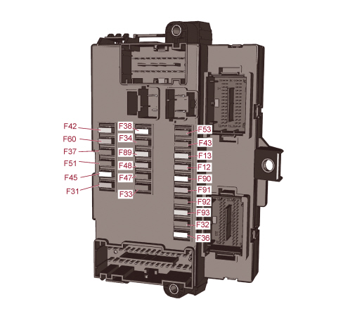
The following table describes the Body Computer Node fuses.
|
F12 |
7,5 |
Right dipped beam headlight |
|
F13 |
7,5 |
Left dipped headlight |
|
F31 |
5 |
(INT/A supply) - Engine compartment junction unit relay, dashboard junction unit relay |
|
F32 |
7,5 |
Passenger compartment interior roof light activation |
|
F33 |
20 |
(+ 30 supply) - Battery monitoring sensor for Start & Stop versions |
|
F34 |
20 |
Minibus interior lights (emergency) |
|
F36 |
10 |
(+30 supply) - Radio, Compressor for climate control, Alarm, Chronotachograph, Battery shut-down control unit, Webasto additional heater timer, TUM control unit |
|
F37 |
7,5 |
(INT supply) - Brake light control (main), Third brake light, Instrument panel, TUM control unit |
|
F38 |
20 |
(+ 30 supply) - Central locking Door locking |
|
F42 |
5 |
(INT supply) - ABS, ASR, ESP, Brake light control (secondary) |
|
F43 |
20 |
(INT supply) - Windscreen wiper |
|
F47 |
20 |
Driver side electric windows |
|
F48 |
20 |
Passenger side electric windows |
|
F49 |
5 |
(INT supply) - Parking sensor control unit, radio, steering wheel controls, central control panel, driver side control panel, auxiliary panel, battery disconnecting control unit |
|
F50 |
7,5 |
(INT supply) - Airbag node |
|
F51 |
5 |
(INT supply) - Climate control node, power steering control unit, reversing lights, diesel filter water sensor, flow meter, tachograph |
|
F53 |
7,5 |
(+ 30 supply) - Instrument panel |
|
F89 |
- |
Not used |
|
F90 |
7,5 |
Left main beam headlight |
|
F91 |
7,5 |
Right main beam headlight |
|
F92 |
7,5 |
Left fog light |
|
F93 |
7,5 |
Right fog light |
ENGINE COMPARTMENT CONTROL UNIT (CVM)
Characteristics
The Engine Compartment Junction Unit (CVM) is a junction unit with sheared circuits, installed in the engine compartment, which contains fuses and relays and performs an interconnection function between the front wiring, radiator and battery positive.
These wirings are connected to the control unit through fixed couplings. These couplings can be easily reached as they are positioned to facilitate fitting or removal operations.
There is a fastening on the lower cover for sealed fuse holder connectors (maxi and auto type).
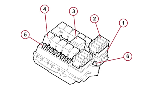
1. Engine Compartment Junction Unit Mounting (CVM);
2. System protective maxifuse;
3. Maxi type relay switch;
4. Micro type relay switch;
5. System protective mini fuses;
6. Connector for connection between Battery Control Unit (CBA) and Engine Compartment Junction Unit (CVM).
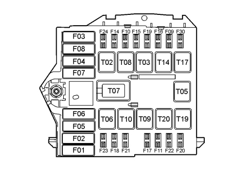
The following figure illustrates the fuses and relay switches in the engine compartment junction unit (CVM).
Fuses
|
F01 |
40 |
Braking System Node (NFR) electric pump |
|
F02 |
50 |
Glow plug pre-heating control unit |
|
F03 |
30 |
Ignition switch |
|
F04 |
30 |
Headlight washer pump |
|
F05 |
20 |
(+ 30 supply) Optional Wiring Module (MCO) for the protection of the following circuits: Additional Webasto Heater, Minibus, Ambulance, starting management relay switch with Start&Stop system |
|
F05 |
50 |
(+ 30 supply) Optional Wiring Module (MCO) for the protection of the following circuits: Robotised Gearbox, Additional Webasto Heater (Versions with robotised gearbox) |
|
F06 |
40 |
(+ 30 supply) Dual-speed engine cooling fan - High speed |
|
F06 |
60 |
(+ 30 supply) Dual-speed engine cooling fan - High speed (Versions with air conditioning / climate control) |
|
F07 |
40 |
(+ 30 supply) Dual-speed engine cooling fan - Low speed |
|
F07 |
50 |
(+ 30 supply) Dual-speed engine cooling fan - Low speed (Versions with air conditioning / climate control and Minibus) |
|
F08 |
40 |
Climate control system |
|
F09 |
15 |
Rear power socket |
|
F10 |
15 |
Horns |
|
F11 |
15 |
Engine management system (secondary loads) |
|
F14 |
15 |
Cigar lighter/power socket |
|
F15 |
10 |
Cigar lighter |
|
F16 |
7,5 |
(15/54 supply) Engine Management Node / starting management relay switch for versions with Start&Stop system / starting management relay switch for robotised gearbox versions |
|
F17 |
10 |
Engine management system (main loads) |
|
F18 |
7,5 |
+ 30 supply Engine Management Node / Robotised gearbox control unit |
|
F19 |
7,5 |
Climate control system compressor |
|
F20 |
30 |
Windscreen wiper |
|
F21 |
15 |
Fuel pump |
|
F22 |
20 |
Engine management system (main loads) |
|
F23 |
30 |
+ 30 supply Braking System Node (solenoid valve unit) |
|
F24 |
15 |
(15/54 supply) Auxiliary panel (ambulance version) / Electric window and mirror movement controls |
|
F30 |
15 |
Mirrors demisting |
Relay switches
|
T02 |
30 / micro |
Current socket/cigar lighter |
|
T03 |
20 / micro |
Horns |
|
T05 |
20 / micro |
Climate control system compressor |
|
T06 |
30 / micro |
Engine cooling fan (high speed) |
|
T07 |
50 / Maxi |
Engine cooling fan (low speed) |
|
T08 |
30 / micro |
Climate control system |
|
T09 |
30 / micro |
Injection system main relay |
|
T10 |
20 / micro |
Fuel pump |
|
T14 |
20 / micro |
Mirrors demisting |
|
T17 |
30 / micro |
Rear power socket |
|
T19 |
30 / micro |
Windscreen wiper |
|
T20 |
30 / micro |
Starting management relay (Versions with robotised gearbox) |
Engine compartment junction unit pin out
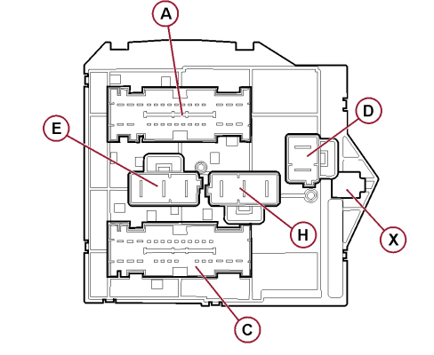
The rear view of the engine compartment junction unit is illustrated below (CVM), with the various connectors highlighted.
B001A connector pin out (brown 32 pin, Front)
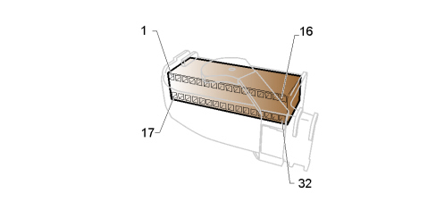
|
1 |
Supply from F09 / T17 for rear power socket |
|
2 |
+30 power supply from F18 for robotised gearbox control unit |
|
3 |
Contact input 30 starting management relay T20. (+50 supply) from ignition switch (versions with robotised gearbox) |
|
4 |
Supply from F30 / T14 for left mirror defrosting |
|
5 |
Supply from F30 / T14 for right mirror defrosting |
|
6 |
Contact input 85 rear power socket relay T17. Negative control for relay coil from Body Computer Node (NBC) |
|
7 |
15/54 supply from F24 for electric window and mirror movement controls |
|
8 |
15/54 supply from F24 for auxiliary panel (ambulance version) |
|
9 |
INT/A supply from F31 of Body Computer Node (NBC) for ambulance setup |
|
10 |
INT/A supply from F31 of Body Computer Node (NBC) for windscreen wiper relay T19 (output) |
|
11 |
INT/A supply from F31 of Body Computer Node (NBC) for: windscreen wiper relay T19 (input) and climate control unit relay T08 |
|
12 |
Contact input 85 cigar lighter/power socket relay T02. Negative control for relay coil from Body Computer Node (NBC) |
|
13 |
Not available |
|
14 |
Contact 86 starting management relay T20 (setup for connection with B001C pin 3) |
|
15 |
Setup for connection with B001C pin 19 |
|
16 |
Supply from F21 / T10 for fuel pump |
|
17 |
Contact input 85 starting management relay T20. Negative control for relay coil from robotised gearbox control unit |
|
18 |
Contact output 87 starting management relay T20. +50 supply for starter (versions with robotised gearbox) - Setup for connection with B001C pin 17 |
|
19 |
Not available |
|
20 |
+15/54 supply from F16 - Setup |
|
21 |
Contact input 85 horn relay T03. Negative control for relay coil from steering wheel switch (clock spring) |
|
22 |
Supply from F14 / T02 for cigar lighter |
|
23 |
Contact input 85 mirror defrosting relay T14. Negative control for relay coil from Body Computer Node (NBC) |
|
24 |
Supply from F15 / T02 - Setup |
|
25 |
Supply from F15 / T02 for front power socket |
|
26 |
Contact input 85 climate control unit relay T08. Earth for relay coil |
|
27 |
Supply from F10 / T03 for single-tone horn |
|
28 |
Supply from F10 / T03 - Setup |
|
29 |
Not available |
|
30 |
+15/54 supply input from ignition switch for fuses F16, F24, cigar lighter/power socket relay coil T02 and mirror defrosting relay coil T14 |
|
31 |
+30 power supply from F03 for ignition switch |
|
32 |
+30 power supply from F23 for Braking System Node (solenoid valve unit) |
B001B connector pin out (grey 3 pin, Front)
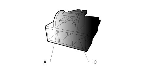
|
A |
+30 power supply from F01 for Braking System Node (NFR) electric pump |
|
B |
+30 supply from F02 for Plug preheating control unit |
|
C |
INT/A supply from F08 / T08 for climate control unit |
B001C connector pin out (black 32 pin, Front)
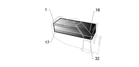
|
1 |
Contact 30 starting management relay T20 (setup for connection with B001A pin 3) |
|
2 |
Supply from F20 / T19 for windscreen wiper |
|
3 |
Contact 86 starting management relay T20. Positive control for relay coil from F16 (versions with robotised gearbox) - Setup for connection with B001A pin 14 |
|
4 |
Supply from F19 / T05 for air conditioning compressor |
|
5 |
Contact input 85 air conditioning compressor relay T05. Negative control for relay coil from Body Computer Node (NBC) |
|
6 |
Contact input 86 windscreen wiper relay T19. INT/A supply for windscreen wiper relay coil from F31 of Body Computer Node (NBC) |
|
7 |
Power supply from F11 / T09 for engine management system (secondary loads) |
|
8 |
15/54 supply from F16 - Setup |
|
9 |
15/54 supply from F16 for Engine Management Node (NCM) - Key-sense |
|
10 |
Contact input 85 main injection system relay T09. Negative control for relay coil from engine Management Node (NCM) |
|
11 |
Contact input 85 fuel pump relay T10. Earth for relay coil |
|
12 |
Contact input 86 main injection system relay T09. Supply for relay coil from F18 |
|
13 |
15/54 supply from F16 - Setup |
|
14 |
Not available |
|
15 |
Not available |
|
16 |
Not available |
|
17 |
Contact 87 starting management relay T20 (setup for connection with B001A pin 18) |
|
18 |
Power supply from F22 / T09 for engine management system (primary loads) |
|
19 |
Setup for connection with B001A pin 15 |
|
29 |
Not available |
|
21 |
Contact input 85 engine cooling fan relay (low speed) T07. Negative control for relay coil from engine Management Node (NCM) |
|
22 |
Contact input 85 windscreen wiper relay T19. Negative control for relay coil from Body Computer Node (NBC) |
|
23 |
+30 supply from F18 for Engine Management Node (NCM) (2.3 JTD version) |
|
24 |
+30 supply from F18 for injection system relay coil T09 |
|
25 |
Not available |
|
26 |
Not available |
|
27 |
Supply from F17/ T09 - Setup for primary load supply |
|
28 |
Contact input 85 engine cooling solenoid valve relay (high speed) T06. Negative control for relay coil from engine Management Node (NCM) |
|
29 |
Contact input 86 of fuel pump relay T10. Positive control for relay coil from engine Management Node (NCM) |
|
30 |
Supply from F21/ T10 - Setup |
|
31 |
Primary injection system load supply from F17 |
|
32 |
Primary injection system load supply from F17 - Setup |
B001D connector pin out (black 2 pin, Front)
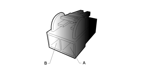
|
A |
+30 supply from F05 for Optional Wiring Module (MCO) |
|
B |
+30 supply from F04 for contact 30 headlight washer pump relay T21 of Optional Wiring Module (MCO) |
B001E connector pin out (blue 3 pin, Radiator)
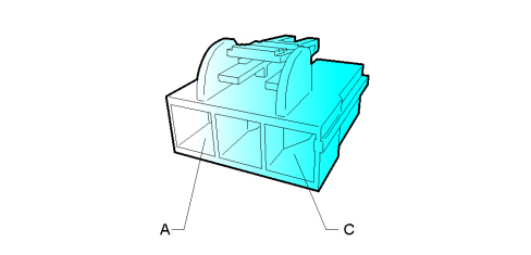
|
A |
Supply from F7/ T07 for engine cooling fan (low speed) |
|
B |
+30 supply from F6 for relay on radiator unit |
|
C |
Supply from F6 / T06 for engine cooling fan (high speed) |
B001X Connector pin out (battery positive)
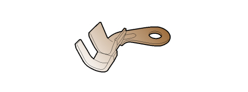
|
1 |
Connection to battery positive from F70 of Battery Control Unit CBA |
BATTERY CONTROL UNIT (CBA)
Characteristics
The Battery Control Unit (CBA) in the wiring diagrams is a power distribution control unit located directly on the battery.
It has a plastic protection that prevents accidental contact with the positive battery terminal.
The CBA is connected to the cab wiring, the OPT cab wiring, the Engine Compartment Junction Unit (CVM) supply connector and the positive battery lead for the starting/recharging circuit.
The Battery Control Unit fuses are illustrated below.
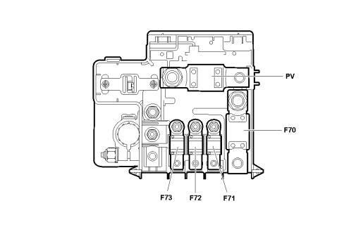
|
F70 |
150 |
+30 supply Engine Compartment Junction Unit - CVM - |
|
F71 |
80 |
+30 supply Body Computer Node (NBC) - CPL1 - |
|
F72 |
70 |
+30 supply Body Computer Node (NBC) - CPL2 - |
|
F73 |
50 |
+30 supply Transformer socket - TRASF - |
|
PV |
CAL4 |
+30 starter supply |

|
To prevent damage to the vehicle when changing fuses, it is very important to tighten the nuts fixing the fuses and the electrical connections correctly to torque.
For further details,
Op. 5530B40 SUPPLY BOX ON BATTERY (LINK BATTERY AND FUSE BOX) - R R
|
The following figure shows the Battery Control Unit connections.
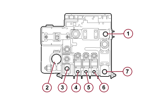
|
1 |
B099B |
Battery positive |
Starter supply |
|
2 |
- |
- |
Battery positive pole |
|
3 |
B099F |
Left longitudinal wiring |
Self-levelling suspension fuse supply |
|
4 |
B099E |
OPT cab wiring |
Transformer socket supply |
|
5 |
B099C |
Cab wiring |
Supply for Body Computer Node (NBC) - CPL2 - |
|
6 |
B099D |
Cab wiring |
Supply for Body Computer Node (NBC) - CPL1 - |
|
7 |
B099A |
Battery positive |
Supply for engine compartment junction unit (CVM) |
Battery control unit (cba) minibus version (2.3 jtd / 3.0 jtd)
The control unit on the battery (CBA) available for the Minibus versions differs from the one fitted on the other vehicles due to the adoption of a "battery disconnector" (SB) relay switch that interrupts the electrical power supply in the case of:
-
intervention of the inertia switch (FIS);
-
pressing the emergency button (if present) located on the ceiling, driver's side.
In these emergency conditions, the engine switches off because, in addition to the electrical supply, the flow of fuel from the tank is interrupted.
The "battery disconnector" relay switch prevents the passengers and the vehicle from being harmed if there is a fire caused by a short circuit or an accident.
This device makes it possible to automatically activate several safety functions that are useful for identifying the vehicle on the road (activation of side lights and hazard warning lights) and exiting from it in emergency conditions (switching on of internal roof lights and unlocking of the doors).
The power supply for the Body Computer (safety function management and control unit) remains active in order to activate these devices.
The tachograph is constantly active during these emergency conditions.
To restore the system's electrical power supply, the inertia switch must be reset and/or the automatic intervention button for danger conditions restored to the rest position; later on, the yellow button located on the Battery Control Unit (CBA) battery disconnector relay switch must be pressed, working on the battery drip tray.
The Battery Control Unit fuses for this version are illustrated below.
The "Battery disconnector" relay switch is also highlighted in the figure (SB reference).
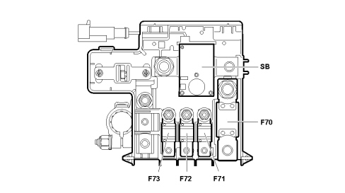
|
F70 |
150 |
+30 supply Engine Compartment Junction Unit - CVM - |
|
F71 |
50 |
+30 supply Transformer socket - TRASF - |
|
F72 |
50 |
+30 supply Body Computer Node (NBC) - CPL2 - |
|
F73 |
70 |
+30 supply Body Computer Node (NBC) - CPL1 - |
The following figure shows the Battery Control Unit connections.
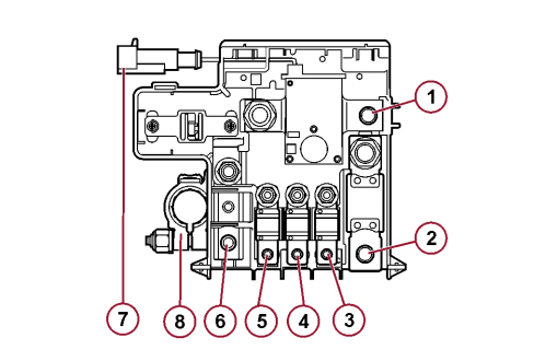
|
1 |
B099B |
Battery positive |
Starter supply |
|
2 |
B099A |
Battery positive |
Supply for engine compartment junction unit (CVM) |
|
3 |
B099E |
OPT cab wiring |
Transformer socket supply |
|
4 |
B099C |
Cab wiring |
Supply for Body Computer Node (NBC) |
|
5 |
B099D |
Cab wiring |
Supply for Body Computer Node (NBC) |
|
6 |
B099F |
Left longitudinal wiring |
Self-levelling suspension fuse supply |
|
7 |
- |
- |
Battery positive pole |
|
8 |
B099G |
Cab wiring |
Negative signal from inertia switch and/or emergency button for battery disconnector relay switch |
Internal wiring diagram
The following figure shows the internal electrical wiring of the Battery Control Unit for this version.
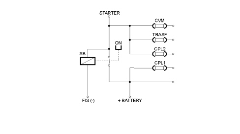
OPTIONAL WIRING CONTROL UNIT (CCO) AND TRANSFORMER SOCKET
Characteristics
The optional wiring control unit CCO is located on the right side of the cab, on the rear post of the front passenger side door.
Depending on the version and the structure of the vehicle for the installer versions, this control unit may feature one or two modules and an additional socket known as a "transformer socket" (or "bodywork socket") - P125 in the wiring diagrams. In addition, in the compartment where it is housed, there may be additional components (fuses and relays) for specific functions relating to particular versions (people carrier).
BASIC and People Carrier variants CCO view
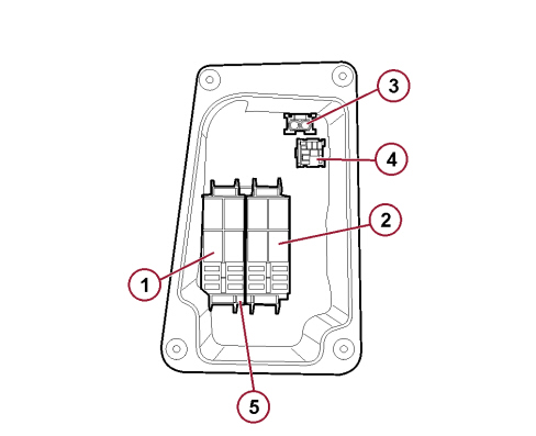
1. Module 1 for Optional Wiring Control Unit (CCO)
2. Module 2 for Optional Wiring Control Unit (CCO)
3. Exterior side marker light fuse
4. External relay switch (T69) side marker lights
5. Cable input side.
Transformer - Leisure time variants CCO view
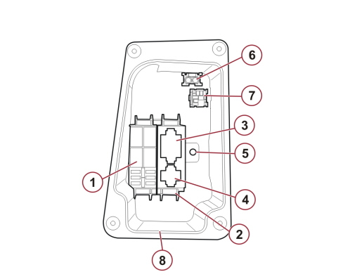
1. Module 1 for Optional Wiring Control Unit (CCO)
2. Transformer socket bracket
3. Connector P125A for transformer socket
4. Connector P125B for transformer socket
5. Connector P125C for transformer socket
6. Exterior side marker light fuse
7. External relay switch (T69) side marker lights
8 Cable input side
Transformer - People Carrier variants CCO view
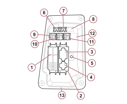
1. Module 1 for Optional Wiring Control Unit (CCO)
2 . Transformer socket bracket
3. Connector P125A for transformer socket
4 . Connector P125B for transformer socket
5. Connector P125C for transformer socket
6 . External fuse A side marker lights
7. External fuse B additional passenger compartment air fan
8 . External fuse C additional air conditioning control panel
9 . External relay switch (T69) side marker lights
10 . External relay switch (T23) additional passenger compartment air fan
11. Relay switch (T24) for low speed fan engagement (additional air conditioning)
12. Relay switch (T29) for additional air conditioning enablement
13. Cable input side
Transformer - Minibus variants CCO view
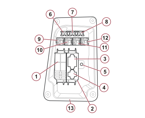
1. Module 1 for Optional Wiring Control Unit (CCO)
2. Transformer socket bracket
3 . Connector P125A for transformer socket
4. Connector P125B for transformer socket
5. Connector P125C for transformer socket
6 . External fuse A side marker lights
7 . External fuse B additional passenger compartment air fan
8. External fuse C additional air conditioning control panel
9 . External relay switch (T69) side marker lights
10 . Relay switch (T67) for internal intake
11 . Relay switch (T67) for internal ventilation
12 . Relay switch (T29) for additional air conditioning supply
13. Cable input side
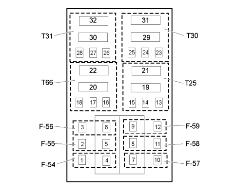
Module 1 fuses
|
F54 |
15 |
INT/A supply for internal ventilation / intake (Minibus version) |
|
F55 |
15 |
INT/A supply for heated seats |
|
F56 |
15 |
INT/A supply for 12 V socket (people carrier transformer version) |
|
F57 |
10 |
+30 supply for additional heater solenoid valve / + 30 supply for additional front heater (Minibus versions) / Additional heater enablement |
|
F58 |
15 |
+30 supply for right heated rear window |
|
F59 |
15 |
+30 supply for left heated rear window |
|
F60 |
- |
Free |
|
F61 |
- |
Free |
|
F62 |
- |
Free |
|
F63 |
10 |
+30 supply for additional air conditioning temperature controls |
|
F64 |
- |
Free |
|
F65 |
30 |
Additional passenger compartment air fan motor supply (additional air conditioning) |
Module 2 fuses
|
F60 |
- |
Free |
|
F61 |
- |
Free |
|
F62 |
- |
Free |
|
F63 |
10 |
+30 supply for additional air conditioning temperature controls |
|
F64 |
- |
Free |
|
F65 |
30 |
Additional passenger compartment air fan motor supply (additional air conditioning) |
External fuses
|
A |
10 |
+30 supply for side marker lights |
|
B |
30 |
+30 supply for additional passenger compartment air fan (people carrier transformer version) |
|
C |
10 |
+ 30 supply for Additional air conditioning temperature controls (people carrier transformer version) |
Module 1 relay switches
|
T25 |
10 - 20 / Micro |
Interior lights (Minibus version) |
|
T30 |
20 / Micro |
Heated rear window |
|
T31 |
30 / Micro |
Supply for additional heater solenoid valve / Supply for additional front heater (Minibus versions) / Additional heater enablement |
|
T66 |
30 / Micro |
Heated seats / Fan aspirator motor for interiors (Minibus versions) / 12 V socket (people carrier transformer version) |
Module 2 relay switches
|
T23 |
30 / Micro |
Additional passenger compartment air fan (additional heater) |
|
T24 |
30 / Micro |
First speed activation for additional air conditioning |
|
T29 |
30 / Micro |
Additional air conditioning enablement |
|
T32 |
30 / Micro |
Free |
External relay switches
|
T23 |
30 / Micro |
Additional air fan for additional passenger compartment heater (people carrier transformer variant) |
|
T24 |
30 / Micro |
First speed activation for additional air conditioning (people carrier transformer variant) |
|
T67 |
10 - 20 / Micro |
Internal intake (Minibus version) |
|
T68 |
10 - 20 / Micro |
Internal ventilation (Minibus version) |
|
T69 |
30 / Micro |
Side marker lights |
Optional wiring control unit cco pin-out
B098A Module 1 connector PIN-OUT (32 pin, OPT cab)
|
1 |
F54 fuse output. Aspirator/fan motor supply for interiors (Minibus version) |
|
2 |
Heated seat supply from fuse F55 |
|
3 |
Supply for 12 V socket from F56 (people carrier / transformer versions) |
|
4 |
F54 fuse input - Setup |
|
5 |
Fuse input F54, F55 and F56. INT/A supply from relay T66 |
|
6 |
F56 fuse input - Setup |
|
7 |
F57 fuse input. +30 supply from Body Computer Node (NBC) |
|
8 |
Fuse input F58 and F59. +30 supply for left and right heated rear window |
|
9 |
F59 fuse input - Setup |
|
10 |
F57 fuse output. Supply for additional heater enablement relay (T31) |
|
11 |
F58 fuse output. +30 supply for right heated rear window |
|
12 |
F59 fuse output. +30 supply for left heated rear window |
|
13 |
Contact 86 interior light relay coil (T25). +30 supply from F36 of Body Computer Node (NBC) - (Minibus version) |
|
14 |
Not connected |
|
15 |
Contact 85 interior light relay coil (T25). Negative control for coil of relay T25 from Body Computer Node (NBC) |
|
16 |
Contact 86 relay coil (T66). INT/A supply from F31 of Body Computer Node (NBC) |
|
17 |
Not connected |
|
18 |
Contact 85 relay coil (T66). Earth for relay coil |
|
19 |
Contact 87 interior light relay coil (T25). +30 supply for Auxiliary Panel |
|
20 |
Contact 87 relay (T66). INT/A supply for fuses F54, F55 and F56 |
|
21 |
Contact 30 interior light relay (T25). +30 supply from F36 of Body Computer Node (NBC) - (Minibus version) |
|
22 |
Contact 30 relay (T66). Supply from maxifuse F72 from Body Computer Node (NBC) |
|
23 |
Contact 86 heated rear window relay coil (T30). INT/A supply from F31 of Body Computer Node (NBC) |
|
24 |
Not connected |
|
25 |
Contact 85 heated rear window relay coil (T30). Negative control for relay coil from Body Computer Node (NBC) |
|
26 |
Contact 86 relay coil (T31). INT/A supply from F31 of Body Computer Node (NBC) |
|
27 |
Not connected |
|
28 |
Contact 85 relay coil (T31). Negative signal for coil of relay T31 from driver side control panel |
|
29 |
Contact 87 heated rear window relay (T30). +30 supply for fuses F58 and F59 protecting left and right heated rear window |
|
30 |
Contact 87 relay (T31). +30 supply for additional heater solenoid valve, additional air conditioning enablement, +30 supply for additional front heater (Minibus versions) |
|
31 |
Contact 30 heated rear window relay (T30). +30 supply from F72 of Battery Control Unit (CBA) |
|
32 |
Contact 30 relay (T31). +30 power supply from F57 |
Modulo 2 pin out (B098B connector)
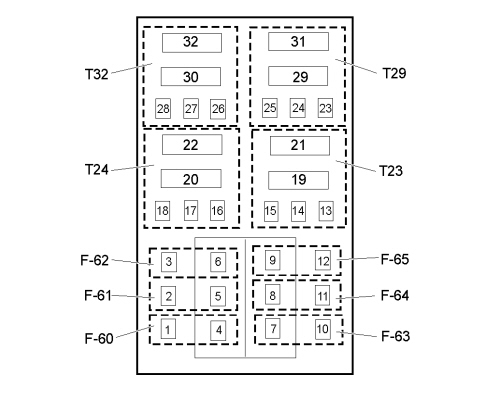
|
1 |
Not connected |
|
2 |
Not connected |
|
3 |
Not connected |
|
4 |
Not connected |
|
5 |
Not connected |
|
6 |
Not connected |
|
7 |
Not connected |
|
8 |
Fuse input F63 and F65. +30 supply from Body Computer Node (NBC) |
|
9 |
Not connected |
|
10 |
F63 fuse output. +30 supply for additional air conditioning temperature controls |
|
11 |
Not connected |
|
12 |
F65 fuse output. +30 supply for additional passenger compartment air fan relay (T23) |
|
13 |
Contact 86 additional passenger compartment air fan relay coil (T23). INT/A supply from F31 of Body Computer Node (NBC) |
|
14 |
Contact 87a additional passenger compartment air fan relay coil (T23). Not connected |
|
15 |
Contact 85 additional passenger compartment air fan relay coil (T23). Earth for relay coil T23 |
|
16 |
Contact 86 relay coil (T24). INT/A supply from F31 of Body Computer Node (NBC) |
|
17 |
Contact 87a relay coil (T24). Not connected |
|
18 |
Contact 85 relay coil (T24). Negative signal for coil of relay T24 from additional air conditioning temperature controls (CMD RELAY 1) |
|
19 |
Contact 87 additional passenger compartment air fan relay coil (T23). +30 supply for additional passenger compartment air fan |
|
20 |
Contact 87 relay (T24). Power earth |
|
21 |
Contact 30 additional passenger compartment air fan relay (T23). +30 power supply from F65 |
|
22 |
Contact 30 relay (T24). Earth for additional passenger compartment air fan first speed. |
|
23 |
Contact 86 additional air conditioning enablement relay coil (T29). +30 supply from relay (T31) |
|
24 |
Not connected |
|
25 |
Contact 85 additional air conditioning enablement relay coil (T29). Earth for relay coil T29 |
|
26 |
Not connected |
|
27 |
Not connected |
|
28 |
Not connected |
|
29 |
Contact 87 additional air conditioning enablement relay (T29). Power earth |
|
30 |
Not connected |
|
31 |
Contact 30 additional air conditioning enablement relay (T29). Negative enablement signal for additional air conditioning |
|
32 |
Not connected |
TRANSFORMER SOCKET
The transformer socket (or "bodywork socket") is available as an optional component and has the function of facilitating the conversion of the vehicle by installers for multiple requirements, providing the repetition of various signals, including the two CAN-B cables.
Transformer socket connector pin-out
P125A connector PIN-OUT (white 15 pin, OPT cab)
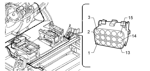
|
1 |
Additional brake light |
|
2 |
D+ (active to earth) |
|
3 |
Vehicle speed repetition (VSO) |
|
4 |
Lock locking control |
|
5 |
Lock unlocking control |
|
6 |
Side and rear door status signal |
|
7 |
Roof light timed SBMT supply 20 W driver |
|
8 |
Negative roof lights control (dimmed) |
|
9 |
B-CAN A |
|
10 |
B-CAN B |
|
11 |
Negative relay control unit for side lights (side markers) |
|
12 |
Additional air conditioning activation request (A/C request) |
|
13 |
INT supply from F49 of Body Computer Node (NBC) |
|
14 |
Additional heater control (A/C rear) |
|
15 |
Not connected |
P125B connector PIN-OUT (white 6 pin, OPT cab)
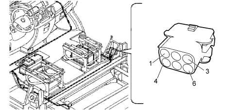
|
1 |
Permanent 12 V supply (+30) for radio |
|
2 |
Rear LH speaker + |
|
3 |
Rear LH speaker - |
|
4 |
Rear RH speaker + |
|
5 |
Rear RH speaker + |
|
6 |
Not connected |
P125C connector PIN-OUT (black 2 pin, OPT cab)
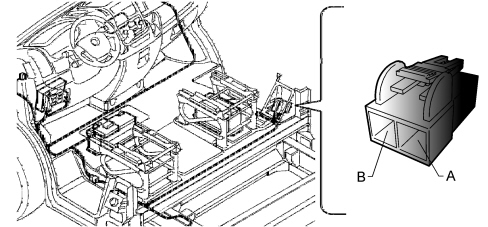
|
A |
+30 power supply from F73 of Battery Control Unit (F71 for Minibus versions) |
|
B |
Power earth |
OPTIONAL WIRING MODULE (MCA)
The Optional Wiring Module (MCA) or additional system fuse box (B046) is used in vehicle versions with robotised gearbox and for the ambulance and minibus versions.
It incorporates the protective fuses for the additional Webasto heater
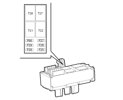
Fuses
|
F25 |
20 |
Additional Webasto heater control unit supply |
|
F26 |
30 |
+30 supply for robotised gearbox pump |
|
F27 |
20 |
+30 supply for internal fan with additional Webasto heater |
|
F28 |
7,5 |
Auxiliary control panel supply (Ambulance version) |
|
F29 |
20 |
Sirens (ambulance version) |
|
F66 |
20 |
Flashing (ambulance version) |
Relay switches
|
T21 |
30 / Micro |
Headlight washers |
|
T22 |
30 / Micro |
Blow-By |
|
T26 |
10 - 20 / Micro |
Deviator (Minibus version) |
|
T27 |
20 / Micro |
Free |
Optional wiring control unit cco pin-out
B046 connector PIN-OUT (32 pin, front)
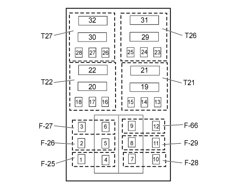
|
1 |
F25 fuse output. Battery supply for additional Webasto heater control unit |
|
2 |
F26 fuse output. +30 supply for robotised gearbox pump |
|
3 |
F27 fuse output. +30 supply controlled internal passenger compartment fan from Webasto relay switch (versions with additional Webasto heater) |
|
4 |
Not connected |
|
5 |
F25 fuse input. + 30 supply from F05 of Engine Compartment Junction Unit (CVM) |
|
6 |
Not connected |
|
7 |
Not connected |
|
8 |
F29 fuse input. + 30 supply from F05 of Engine Compartment Junction Unit (ambulance version) |
|
9 |
Not connected |
|
10 |
F28 fuse output. INT supply for Ambulance Control Panel |
|
11 |
F29 fuse output. +30 supply for siren activation relay switch (ambulance version) |
|
12 |
F66 fuse output. +30 supply for flashing lights activation relay switch (ambulance version) |
|
13 |
Contact 86 headlight washer relay coil (T21). Negative control for relay coil from Body Computer Node (NBC) |
|
14 |
Not connected |
|
15 |
Contact 85 headlight washer relay coil (T21). INT/A supply for relay coil from F31 of Body Computer Node (NBC) |
|
16 |
Contact 86 Blow-By relay coil (T22). Supply for relay coil from F17 of Engine Compartment Junction Unit (CVM) |
|
17 |
Not connected |
|
18 |
Contact 85 Blow-By relay coil (T22). Negative signal for relay coil from engine Management Node (NCM) |
|
19 |
Contact 87 headlight washer relay coil (T21). Supply for headlight washer electric pump motor |
|
20 |
Contact 87 Blow-By relay (T22). Supply for oil vapour heating resistance |
|
21 |
Contact 30 headlight washer relay (T21). Supply from F04 of Body Computer Node (NBC) |
|
22 |
Contact 30 Blow-By relay (T22). Supply from F17 of Engine Compartment Junction Unit (CVM) |
|
23 |
Contact 86 relay coil T26. +30 supply from F36 of Body Computer Node (NBC) - (Minibus version) |
|
24 |
Contact 87a relay coil T26. Earth for fuel pump from inertia switch |
|
25 |
Contact 85 relay coil T26. Negative signal from hazard warning lights control |
|
26 |
Contact 86 relay coil T27. Not connected |
|
27 |
Contact 87a relay coil T27. Not connected |
|
28 |
Contact 85 relay coil T27. Not connected |
|
29 |
Contact 87 relay T26. Negative emergency signal for battery disconnector |
|
39 |
Contact 87 relay T27. Not connected |
|
31 |
Contact 30 relay T26. Earth through inertia switch |
|
32 |
Contact 30 relay T27. Not connected |
CAN (TUM) GATEWAY FOR FITTER/INSTALLER VERSIONS
Description
Fitters/installers needed to fit some electronic devices not compatible with those installed in factory, this resulted in the need to use the CAN (CAN-B and CAN-C) gateways between the applications typical of Fiat Auto (FGA) and the world of FMS (Fleet Management System Interface).
The FMS interface is a standard system, developed by the main European manufacturers of commercial vehicles to make possible computerised applications, independent of the manufacturers.
The TUM (Truck Upfitter Module) control unit is therefore a device that intercepts and stores data and signals (sniffer) which acts as a gateway between the vehicle’s B-CAN and C-CAN and the external high speed network that sends messages according to the FMS standard.
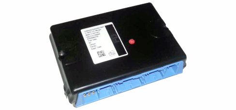
TUM control unit
Operation of the TUM gateway involves:
-
transformation 1:1 of some signals of the vehicle message map to the FMS standard – Direct Gateway -;
-
the use of various vehicle signals to calculate the required FMS signals not present directly on the vehicle network – Indirect Gateway -.
The operating diagram of the Gateway is shown below.
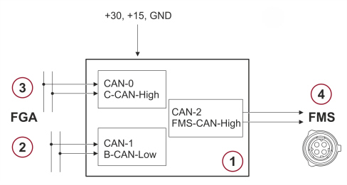
1. TUM control unit
2. CAN-B line (CAN-1) - input -
3. CAN-C line (CAN-0) - input/output -
4. FMS-CAN line (CAN-2) - CAN interface connector (SAE J1939) -
A dedicated connecting harness, about 2 metres long, is provided for this application.
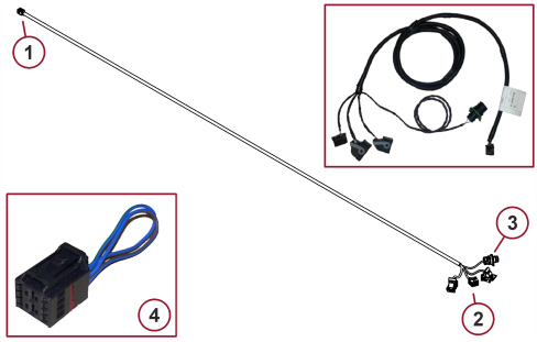
1. Disconnection with vehicle front wiring
2. TUM control unit connectors
3. FMS-CAN interface connector (SAE J1939)
4. Terminal short circuiting coupling (to be used in the event of disconnection – even temporary – of the TUM harness)
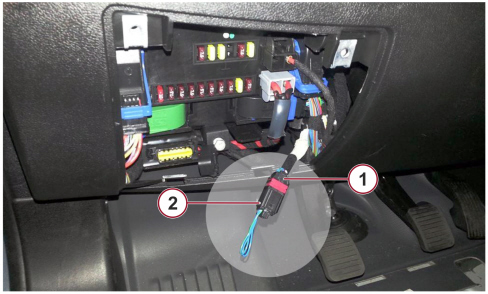
The position of the harness and control unit on the vehicle is chosen by the fitter/installer; the harness can be connected to the vehicle with disconnection of the front wiring in the area under the dashboard, Body Computer side (on the left for LHD versions and on the right for RHD versions).
The only installation restriction for fitters/installers is to place the electronic device in a dry area, because the TUM control unit is not water-proof.
The three possible installation modes are shown below.
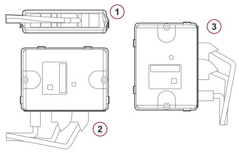
1. Horizontal
2. Vertical (connectors located at the bottom)
3. Vertical (connectors located at the side)
|
|
The disconnected front wiring (1) must of necessity be connected either to the short circuiting coupling (2) or to the TUM kit (connecting harness with the TUM device connected). Otherwise, the vehicle would not operate due to the break in the C-CAN.
|
Tum control unit pin out
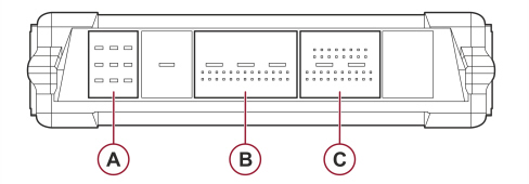
Connector A
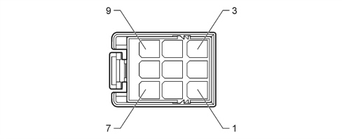
|
2 |
+30 power supply from Body Computer F36 |
|
5 |
GND |
Connector B
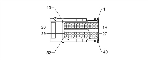
|
1 |
CAN-C H (CAN-0, output) |
|
2 |
CAN-C L (CAN-0, output) |
|
5 |
Trailer presence signal - setup - |
|
13 |
+15 (INT) power supply from Body Computer F37 |
|
14 |
CAN-C H (CAN-0, input) |
|
15 |
CAN-C L (CAN-0, input) |
|
22-24 |
Jumper between pins 22 and 24 for hardware identification |
|
23-26 |
Jumper between pins 23 and 26 for hardware identification |
Connector C
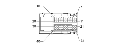
|
12 |
CAN-B B (CAN-1, input) |
|
13 |
CAN-B A (CAN-1, input) |
|
17 |
FMS-CAN L (CAN-2, to connector SAE J1939) |
|
18 |
CAN-B A (CAN-1, output) - setup - |
|
19 |
FMS-CAN H (CAN-2, to connector SAE J1939) |
|
20 |
CAN-B B (CAN-1, output) - setup - |
|
|
Should inter-CAN (FGA-FMS) communication not be available following installation of the TUM device, a jumper must be applied between pins 10 and 17 of connector C of the connection harness to activate the internal terminal resistor (120 ohm) in order to prevent connection problems between devices.
|
Fms-can connector pin out (sae j1939)
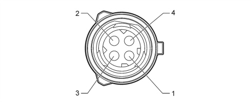
|
1 |
FMS-CAN H (CAN-2, to TUM control unit) |
|
2 |
FMS-CAN L (CAN-2, to TUM control unit) |
For any further detail on electrical connection of the TUM, refer to the dedicated electrical diagrams.
See E1050 CAN CONNECTION LINES
Tum device operation
The following table lists all the signals available on the FMS-CAN (depending on the version/trim level) which are useful for the control units that interface with the TUM device.
|
CCVS |
Parking Brake Switch |
Indicates parking brake engaged |
|
Wheel based speed |
Indicates vehicle speed |
|
Clutch switch |
Indicates clutch pedal pressed |
|
Brake switch |
Indicates brake pedal pressed |
|
Cruise control active |
Indicates Cruise Control active |
|
EEC2 |
Accelerator pedal position 1 |
Indicates accelerator pedal position |
|
Engine Percent Load At Current Speed |
Indicates percentage ratio between engine torque and maximum indicated torque at current engine speed |
|
LFC |
Engine total fuel used |
Indicates total fuel used during vehicle operation |
|
DD |
Fuel Level |
Indicates ratio of fuel volume to total tank volume |
|
EEC1 |
Engine speed |
Indicates engine speed |
|
VDHR |
High resolution total vehicle distance |
Indicates total vehicle distance travelled |
|
ET1 |
Engine coolant temperature |
Indicates temperature of engine coolant |
|
AMB |
Ambient Air Temperature |
Indicates temperature outside of vehicle |
|
LFE |
Fuel Rate |
Indicates quantity of fuel used by engine per time unit |
|
Instantaneous Fuel Economy |
Indicates ratio between quantity of fuel used and current vehicle speed |
|
SERV |
Service distance |
Indicates distance that can be travelled by vehicle before scheduled servicing |
|
HOURS |
Total engine hours |
Indicates total engine operating time |
|
DC1 |
Position of doors |
Indicates current door status |
|
AS |
Alternator Status 1 |
Indicates current alternator status |
|
ETC2 |
Selected Gear |
Indicates next awaited gear |
|
Current Gear |
Indicates current gear |
|
TD |
Minutes |
Indicates minutes |
|
Hours |
Indicates hours |
|
Month |
Indicates month |
|
Day |
Indicates day |
|
Year |
Indicates year |
|
FMS1 |
High beam, main beam |
Indicates active main beam status |
|
Low beam |
Indicates active dipped headlight status |
|
Turn signals |
Indicates active direction indicator status |
|
Hazard warning |
Indicates active hazard light status |
|
Parking Brake |
Indicates parking brake engaged |
|
Brake failure/brake system malfunction |
Indicates braking system fault |
|
Hatch open |
Indicates rear door not shut |
|
Fuel level |
Indicates fuel reserve warning light on |
|
Engine coolant temperature |
Indicates engine coolant overheating warning light on |
|
Battery charging condition |
Indicates insufficient battery charge warning light on |
|
Engine oil |
Indicates insufficient engine oil pressure warning light on |
|
Position lights, side lights |
Indicates active side light status |
|
Front fog light |
Indicates active fog light status |
|
Rear fog light |
Indicates active rear fog light status |
|
Engine / Mil indicator |
Indicates EOBD/injection system failure warning light on |
|
Service, call for maintenance |
Indicates that the scheduled servicing indicator is displayed on the instrument |
|
Transmission failure/malfunction |
Indicates transmission system fault |
|
Anti-lock brake system failure |
Indicates ABS failure warning light on |
|
Worn brake linings |
Indicates brake pad wear warning light on |
|
Malfunction / general failure |
Indicates general failure warning light on |
|
Height Control (Levelling) |
Indicates that the active suspension indicator is displayed |
|
Engine Emission system failure (Mil indicator) |
Indicates particulate filter blocked warning light on |
|
ESC indication |
Indicates stability control warning light on |
|
TCO1 |
Tachogr. vehicle speed |
Indicates vehicle speed stored by chronotachograph |
|
DC2 |
Open Status Door 1 |
Indicates driver door status |
|
Open Status Door 2 |
Indicates passenger door status |
|
Open Status Door 3 |
Indicates rear door(s) status |
|
Open Status Door 4 |
Indicates sliding side door status |
|
Open Status Door 5 |
Indicates sliding side door status |
|
FMS |
Requests supported |
Indicates whether the TUM can respond to requests from external FMS module |
|
Diagnostics supported |
Indicates whether the TUM supports requests for sending diagnosis information |
|
FMS-standard SW - version supported |
Indicates the version of the FMS Standard supported by the TUM |
|