
|
 Removing
(
Refitting Removing
(
Refitting )
)
- Remove left tyre spring. Op. 4430C60 PNEUMATIC SPRING (ONE) LEFT OR RIGHT FOR SELF-LEVELLING SUSPENSION SYSTEM - R.R. |
|
- Remove the control unit module/compressor guard. Op. 4430B13 SELF-LEVELLING SUSPENSION SYSTEM COMPRESSOR/CONTROL UNIT MODULE GUARD - R.R. |
|
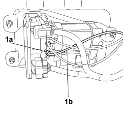 |
1. On the control unit module/compressor, unscrew connector (1a) of green pipe (1b) carrying compressed air to the left tyre spring. |
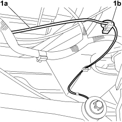 |
1. Loosen pipe (1a) from clips (1b) securing it to the frame and remove. |
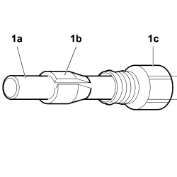 |
1. Remove air pipe (1a) and inner tapered sealing ring (1b), then pull out quick coupling (1c) (from both ends of the pipe).
|

|
|
Refitting
(
Removing
)
- Check that the pipe is not damaged; if it is, replace it. |
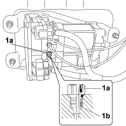 |
1. Screw a new quick coupling (1a) along with associated inner tapered sealing ring (1b), onto the control unit module/compressor.
|

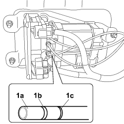 |
1. Two reference lines (1b) and (1c) are present on the end of air pipe (1a); insert air pipe into quick coupling (1d) of the control unit module/compressor, to a depth of around 20 mm, that is, as far as necessary so that only line (1c) is visible.
|
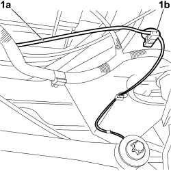 |
1. Fix pipe (1a) to associated frame fixing clips (1b). |
|
|
- Replace the control unit module/compressor guard. Op. 4430B13 SELF-LEVELLING SUSPENSION SYSTEM COMPRESSOR/CONTROL UNIT MODULE GUARD - R.R. |
|
- Position the left tyre spring. Op. 4430C60 PNEUMATIC SPRING (ONE) LEFT OR RIGHT FOR SELF-LEVELLING SUSPENSION SYSTEM - R.R. |
|