MAIN FEATURESThe control panel is installed behind the steering wheel. Its position guarantees maximum visibility/legibility of the information for the driver in all vehicle usage conditions (day/night) without reflections, distortions or double images. There are two different versions of panels, known as Modal and Comfort. The differences between the two versions refer to:
View of instrument panelModale Version 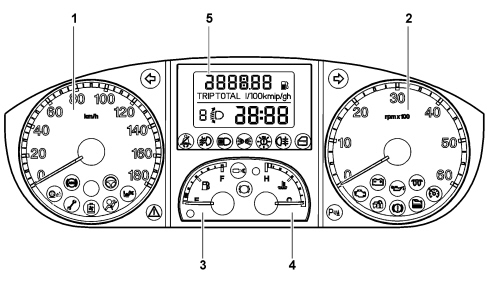
1 - Speedometer 2 - Rev counter 3 - Fuel level gauge (with reserve warning light) 4 - Engine coolant temperature gauge (with overheating warning light) 5 - Digital display Comfort Version 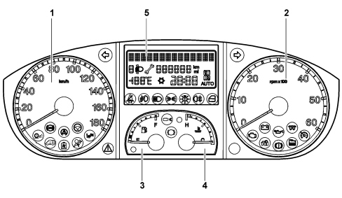
1 - Speedometer 2 - Rev counter 3 - Fuel level gauge (with reserve warning light) 4 - Engine coolant temperature gauge (with overheating warning light) 5 - Multifunction display COMPOSITIONThe control panel is a node for the B-CAN and includes the gauges, which have stepping motors, for:
There are numerous warning lights with LEDs in the panel to display all the information which might be useful for the driver. There is a display in the centre which differs according to the version. Modale Version Display 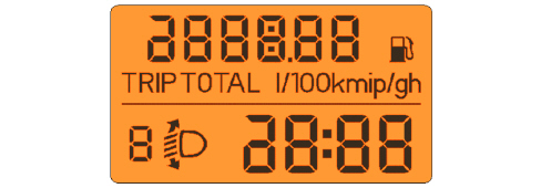
The top line is for displaying:
The two bottom lines in segments are for displaying:
Comfort Version 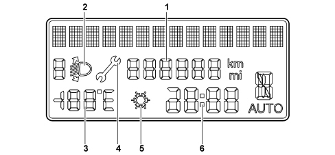
The top line has 14 dot matrix characters (7x5) for the display of:
The two bottom lines in segments are for displaying: 1 - mileometer; 2 - headlight alignment corrector indication; 3 - outside temperature (if fitted); 4 - Service spanner symbol; 5 - "ice" symbol (ice danger) (if fitted); 6 - clock. On both versions there is also a buzzer for signals of varying intensity to warn of:
WARNING LIGHTS IN INSTRUMENT PANELModale versionThe warning lights in use on the Modal version instrument panel are listed below (as well as the warning lights mentioned previously - fuel reserve and engine coolant overheating). 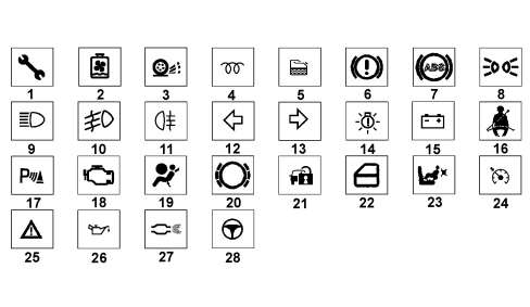
(*) The "general failure" warning light is designed to signal:
Comfort versionThe warning lights in use on the Comfort version instrument panel are listed below (as well as the warning lights mentioned previously - fuel reserve and engine coolant overheating). 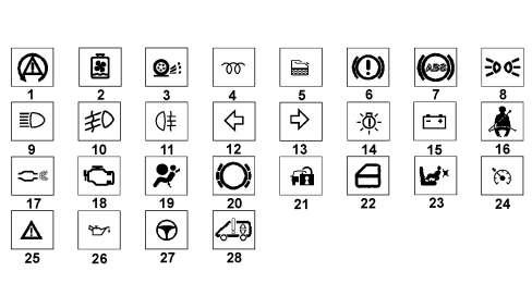
(*) The "general failure" warning light is designed to signal:
REAR VIEW OF INSTRUMENT PANELThe rear view of the instrument panel is illustrated below. 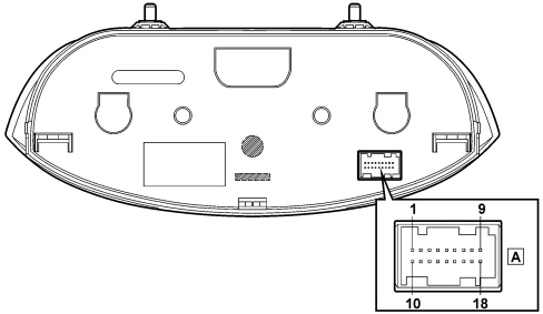
Pin-out
GAUGESSpeedometerThe system calculates the value of the actual vehicle speed, starting with the values supplied by the sensors on the wheels and the value of the actual circumference of the wheels, supplied by the on-board computer. The speedometer reading is produced by means of a stepping motor. The reading at the key on is 0 (zero) km/h (or mph). Rev counterThe control and operating electronics use a microprocessor with the engine rpm reading produced using a stepping motor, guaranteeing precision and continuity throughout the entire scale and a reading in extreme operating conditions. At the key on the indicator is at 0 (zero) RPM and the instrument panel receives the engine rpm information.
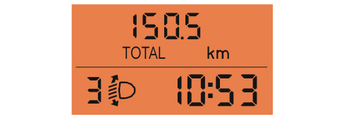
Fuel level gaugeThe control and operating electronics use a microprocessor; the fuel level reading is analogue, produced using a stepping motor. The fuel level is measured by a sensor in the tank which supplies the information to the Body Computer Node. The switching on/off of the fuel reserve warning light in the instrument panel is controlled by the Body Computer; the red area on the gauge corresponding to the start of the "fuel reserve" and the warning light is produced by an amber-coloured LED. The warning light coming on indicates that there are about 10-12 litres of fuel remaining in the tank (depending on the version). A fault in the system is signalled by the gauge showing E (Empty) and the reserve warning light flashing. Engine coolant temperature gaugeThe engine coolant temperature control electronics use a microprocessor with the reading (which is activated at the key on) produced precisely by a stepping motor, with the corresponding red coloured "danger zone". The temperature reading is always guaranteed, even in extreme operating conditions. The (red) engine coolant temperature overheating warning light comes on when the temperature is too high. The analogue gauge reading will be at the end of the scale. If there is a fault with the engine coolant temperature sensor, the instrument panel places the pointer in the rest position at the key off. INITIAL CHECKModale versionWith the front doors closed at the key off, the display shows the clock. If at least one of the front doors is opened at the key off, the display shows the clock and the mileometer. At every Key ON, a check starts on all the electronic control units present on board the vehicle, with some of the warning lights in the panel coming on. A check is also carried out on the various instrument panel warning lights. At the end of the check stage the standard screen appears, displaying the following:
Comfort versionWith the front doors closed at the key off, the display shows the clock. If at least one of the front doors is opened at the key off, the display shows the clock and the mileometer. At every Key ON, a check starts on all the electronic control units present on board the vehicle, with some of the warning lights in the panel coming on. A check is also carried out on the various instrument panel warning lights. At the end of the check stage the standard screen appears, displaying the following:
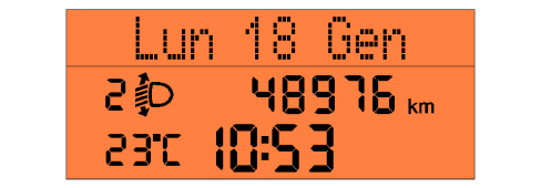
SET-UP MENU FUNCTIONSModale versionThe control panel to the left of the steering wheel contains the buttons for the digital display settings. Pressing the MENU button briefly gives access to the menu and it is possible to move on to the next screen or confirm the choice made. Pressing the button for longer makes it possible to return to the standard screen. The two arrow buttons are used for sliding over the various options (within the menu) or increasing / decreasing the values displayed (during setting operations). The following functions can be set on the modal version:
The vehicle speed limit can be set (km/h or mph) and the driver will be notified when it is exceeded;
The hours and minutes for the clock can be adjusted;
The volume of the buzzer which accompanies the display of the failure / warning can be adjusted;
Either kilometres (km) or mile (mi) can be selected;
The passenger airbag can be activated/deactivated. For more details, See descriptions 5580C AIR BAG SYSTEM
Comfort versionThe control panel to the left of the steering wheel contains the buttons for the multifunction display settings. Pressing the MENU button briefly gives access to the menu and it is possible to move on to the next screen or confirm the choice made. Pressing the button for longer makes it possible to return to the standard screen. The two arrow buttons are used for sliding over the various options (within the menu) or increasing / decreasing the values displayed (during setting operations). The following functions can be set on the multifunction version:
The vehicle speed limit can be set (km/h or mph) and the driver will be notified when it is exceeded;
The sensitivity of the dusk sensor (if present) can be adjusted to 3 levels for the automatic activation of the side lights and/or dipped headlights;
The trip B (trip meter) display can be activated / deactivated;
The clock hours and minutes can be adjusted, as can the display format (12h or 24h);
The day, month and year can be adjusted;
The radio information can be shown on the display (RDS messages or frequency, CD track number, CD number in the case of a CD changer);
There is an option to activate / deactivate the function that automatically locks the doors when a speed of 20 km/h is exceeded;
The units of measurement can be set for "Distances" (km or mi), "Consumption" (km/l, l/100 km or mpg) and "Temperature" (°C or °F);
One of the available languages can be selected for the message display;
The volume of the buzzer which accompanies the display of failures / warnings can be adjusted to 8 different settings;
The volume of the acoustic warning when the left control panel buttons are pressed can be adjusted to 8 different levels;
It allows reactivation of the S.B.R. and can only be displayed once this has been deactivated;
The mileage intervals for services can be displayed;
The passenger airbag can be activated/deactivated.
Interior lights adjustment (dimming)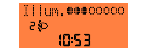
On the Comfort version, brightness can be adjusted to 8 levels (graphs / gauges / control panel display) by pressing the "MODE +" and "MODE -" buttons. The effect of adjusting the brightness (after pressing the buttons) is immediately visible. The dimming value is transmitted by the NQS via the CAN B to allow the brightness value to be sent to the other Nodes. If the side lights are deactivated, the display is 100% lit up and the brightness cannot be adjusted (dimmed). Adjustment is only possible with the exterior lights on. The warning lights are not subject to adjustment (brightness is always 100%). If the brightness is adjusted, the message "Illum" will be shown on the first line of the display. The gradual "switching on" of the brightness adjustment symbols allows the level to be displayed immediately. The setting screen remains for 5 seconds after the last command is given, after which the previous screen is displayed. While the screens relating to the signalling of faults/information are present, the lighting for the display is not subject to adjustment/dimming and the brightness always remains constant at 100% in daytime conditions (side lights deactivated). The "MODE +" and "MODE -" buttons remain activated in order to adjust the brightness of the control panel and the other vehicle components (the first line of the display does not, however, show the message "Illum." and the switching on/off of the brightness adjustment symbols) TRIP COMPUTERMain featuresThe TRIP computer is a specific function that makes it possible to show various information in the control panel display relating to the vehicle's operating status. These scales are summarised in the table below.
The control panel receives the following information (input) to compute these scales:
The unit of measurement for the consumption can be set by the user (km/l or l/100 km or mpg). All information appears individually in the display. Whenever the battery is disconnected and reconnected, all the TRIP values are reset. Measurement unit setting via the menu is maintained at all times. The counting/updating of the TRIP scales only takes place with the engine running. Zeroing by manual reset of one of the TRIP data items automatically resets all the others (apart from RANGE and INSTANTANEOUS FUEL CONSUMPTION). After this, the count for each data item proceeds independently of the rest. The automatic zeroing takes place when:
Range The range indicates the estimated distance (in km or miles) that the car could travel with the fuel currently in the tank, assuming the journey is continued with the same driving style (same fuel consumption conditions). The range is calculated using the following information:
- instant mileage; - fuel level (as a percentage of a full tank);
- instant fuel consumption (in litres/hour); - fuel tank capacity, in litres (calibration parameter entered during the EOL programming - supplier). Distance travelled The distance travelled by the vehicle from the start of the mission is indicated, i.e. from when the user carried out a reset by pressing the relevant button. The indication matches the total odometer reading. Each time the battery is connected and at the start of each new mission (reset) the display will show "0.0", after which the calculated value will be displayed. At each key ON, the value stored at the previous key off is displayed. When the maximum possible distance is reached, the mileage display should be automatically zeroed and, at the same time, there is a total TRIP reset (excluding the Range and Instant Consumption items). The calculation of the Distance Travelled is activated at the key on. The distance reading should be displayed and sent through the CAN along with:
Average fuel consumption Average fuel consumption means the ratio between distance travelled since the start of the mission and number of litres consumed since the start of the mission. The control panel downloads the fuel consumption signal via the CAN and divides it by the distance travelled since the start of the mission. The calculation is only carried out with the engine running (300 rpm). At the start of a new mission, due to the battery being reconnected, the average consumption figure is set to the "predefined average standard consumption" value, personalised for the vehicle/engine type. At the start of a new mission due, on the other hand, to a reset (by the user pressing the dedicated button or a reset of one of the TRIP parameters) the Average Consumption value is set to the "average consumption value calculated during the previous mission". A weighting to be attributed to the above initial value in order to avoid excessive fluctuations in the reading shown during the first few minutes of the mission. The information displayed tends to represent the actual mission consumption condition within 3 minutes and the effect of the standard data becomes nil. The value displayed is equal to "----" for a distance travelled by the vehicle from the start of the mission equal to the parameter 500 m, after which the value calculated will be displayed. At each key on, the value stored at the previous key off is displayed. The displayed average consumption is equal to"----", whenever:
The value is displayed and sent through the CAN with:
Instant fuel consumption The Instantaneous Fuel Consumption refers to the value of litres of fuel consumed per unit of distance travelled by the vehicle during the mission. The value displayed makes the user aware of the differences in fuel consumption connected with the style of driving without varying excessively and/or with inconsistent values. The Instantaneous Fuel Consumption is calculated using the following information:
Average speed The average speed is calculated from the beginning of the mission, as a ratio between distance travelled and trip time. The calculation is only carried out with the engine running (300 rpm). Each time the battery is connected and at the start of each new mission (reset) the display will show "----" for a distance travelled by the vehicle from the start of the mission equal to the parameter 500 m, after which the value calculated will be displayed. At each key on, the value stored at the previous key off is displayed. The displayed average speed is equal to"----", whenever:
The value is displayed and sent on the CAN with:
Travelling time The trip time shows the time elapsed since the start of the mission, i.e. since the user reset the counter by pressing the dedicated button or an automatic reset occurred. Each time the battery is reconnected and at the beginning of each new mission (reset), the display shows "0:00", after which the calculated value is displayed. At each key on, the value stored at the previous key off is displayed. If the vehicle is parked with the engine off (key off), the accumulated trip counter stops but does not reset to zero. The count resumes as soon as the vehicle sets off again (next key on - engine running). The counting of the Journey Time is activated at the key on with the engine running (parameter 300 rpm). Starting at the key on, the Journey Time is indicated in hh:mm and is sent on the CAN with:
When the maximum possible value is reached (99.59), the journey time display should be automatically zeroed and, at the same time, there is a total TRIP reset with the exception of the Range and Instantaneous Consumption items.
Recovery If information is missing (no relevant CAN signals), some of the TRIP data will display the message "not available". If the speed sensor is faulty, all the TRIP counters display dashes "----" together with the data characteristics (with units of measurement) for each item (km or mi for range, km/h or mph for average speed etc.). If the fuel level sensor is faulty, dashes "----" will be displayed for the range figure, together with a description (with the units of measurement) for each figure. If the instantaneous consumption figure is not validated, dashes "----" will be displayed for the Range, Average consumption and Instantaneous consumption, together with a description (with the relevant units of measurement) for each value. If the malfunction disappears, each of the various countdowns continues in its own way; the values downloaded prior to the fault are not reset and the mission is not restarted. Comfort versionThe instrument panel on the Comfort version also includes the "TRIP B" function (trip meter), which allows the display of:
This function is independent of the General TRIP computer and can be excluded through a setting in the menu. On this version, therefore, there are two modes known as "TRIP A" and "TRIP B" respectively. These are capable of monitoring the complete vehicle journey independently of one another. Resetting the General TRIP also resets TRIP B. TRIP B, on the other hand, is reset independently. The resetting takes place by pressing the button for longer than 2 secs. (and not when the button is released). OIL LEVEL READINGModale versionThe gauge shows the level of oil in the engine in a graphic form. When the ignition key is turned ON, the quantity of oil in the engine is displayed by means of five symbols. 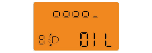
The gradual switching off of the symbols indicates a decreasing oil level. If the oil level is lower than the minimum required value and a top-up is required, the display shows 5 dashes intermittently. After a few seconds, the display of symbols indicating the amount of engine oil will disappear and, if a service is due shortly, the remaining distances will be shown. The "scheduled servicing" warning light (spanner) will also light up on the instrument panel. When the service date is reached, the display shows some dashes. Later on, if the time for the engine oil change is getting close, the top line of the display will show the distance remaining until the next oil change, accompanied by the word "OIL" in the lower part of the display. When the service interval has expired five dashes will be shown on the display. Comfort versionWhen the ignition key is turned ON the top line of the display shows the oil level by five symbols lighting up / switching off. 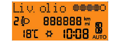
The gradual switching off of the symbols indicates a decreasing oil level. If the oil level is lower than the minimum required value, the display shows a dedicated message indicating minimum engine oil level and the need for a top-up. After a few seconds the display of symbols indicating the amount of the engine oil will disappear and, if a service is due shortly, the remaining distance will be shown plus the "Service" symbol (spanner) will light up in the display. When the service date is reached, the display shows a dedicated message. Later on, if the time for changing the engine oil is getting close, the distance until the next oil change will appear on the display. When the service interval has expired a dedicated warning will be shown on the display. PLANNED MAINTENANCE WARNING (MODAL VERSION)When the next planned maintenance (service) is close, the message is automatically displayed at the key on (after the initial check procedure), followed by the number of kilometres (or miles) until the next service is due. If this value is exceeded the panel shows "----", but this signal stops when the first 1000 km from the expiry date is reached. PLANNED MAINTENANCE WARNING (COMFORT VERSION)The Scheduled Maintenance Plan sets out different service intervals depending on the engine type; this display appears automatically with the ignition ON, starting from 2,000 km (or 1,240 miles) and is re-computed every 200 km (or 124 miles). Oil change notification messages are displayed in the same way. Using the buttons for selecting the menu items on the left control panel it is possible to alternately display the service interval or engine oil change information. Below 200 km servicing indications are more frequent. When the next service is close, when the ignition is turned ON the word "Service" appears in the display followed by the remaining number of kilometres/miles. If this value is exceeded the panel shows "----", but this signal stops after the first 1000 km from the expiry date. Important information
This information is preserved in the memory even if the vehicle battery is disconnected.
Display of messages (comfort version)The messages in the display are divided into 4 different classes:
All messages that come under the 4 categories described above are managed:
When faults occur on the vehicle, the following is shown on the display:
The message is present in the display at the same time as the warning light is on.
The display of faults follows a logic which depends on the priority (high or low) allocated. A very serious malfunction (high priority) immediately interrupts any other information that might have been displayed on the screen. The fault message cycle should be repeated the same number of times as the parameter:
The message disappears at the end of the cycle. It is also proposed again at every key on until the cause of the malfunction that produced the problem is solved. If the problem stops during the display of the first cycle, the message will, however, remain until the end of the actual cycle (minimum display time), to prevent "flash" type displays (the warning light goes out when the problem stops). If the problem disappears during the display (after the first cycle mentioned above), the warning light and the message will go out together. At the end of the last cycle the screen prior to the fault will be shown again but the signal should be kept activated through the warning light in the panel. This should remain on until the cause of the malfunction that produced the fault is resolved. The display cycle can be interrupted in two ways:
If fault events occur simultaneously, the display of faults with high priority takes precedence over low priority faults, which are displayed later on. The information corresponding to the various problems is displayed for one cycle each in rolling mode. If more than one fault with the same priority is present simultaneously, they are displayed for one cycle each in rolling mode. The signalling cycle in the display for information-type messages is repeated 4 times, following the same logic as for low priority fault messages. The display of feedback-type messages, which usually notify the driver of the activation/deactivation of a function they have requested, is managed through the same methods as those described for the display of information messages. Speed limit function A speed limit (with a range of between 30 and 250 km/h in 5 km/h steps; or between 20 and 155 mph in 5 mph steps) can be set and, if it is exceeded, the driver is notified. The message disappears when the warning cycle is over and/or when the speed of the vehicle goes below 5 km/h (or the equivalent value in mph) in relation to the speed limit set. 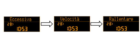
|
||||||||||||||||||||||||||||||||||||||||||||||||||||||||||||||||||||||||||||||||||||||||||||||||||||||||||||||||||||||||||||||||||||||||||||||||||||||||||||||||||||||||||||||||||||||||||||||||||||||||||||||||||||||||||||||||||||||||||||||||||||||||||||||||||||||||||||||||||||||||

