
|
 Removing
(
Refitting Removing
(
Refitting )
)
- Position the vehicle on the lift. Op. 5530B54 - Disconnect the negative battery terminal.
|
|
Op. 7055B91 Op. 7055B51 Op. 7055B56 |
|
|
Op. 1092G15 ENGINE COMPONENT SINGLE BELT MOVING TENSIONER - R.R. WITH BELT REMOVED |
|
|
|
Op. 1064B35 PRESSURIZED AIR SUPPLY PIPE TO WASTE GATE VALVE - R.R. |
|
Op. 1064B36 PRESSURIZED AIR SUPPLY PIPE TO WASTE GATE ACTUATOR - R.R. |
|
Op. 1064B44 WASTE GATE VALVE ACTIVATION SOLENOID VALVE - R.R. |
|
Op. 1064B30 WASTEGATE SOLENOID VALVE MOUNTING BRACKET - R.R. |
|
|
|
|
Op. 1048A42 SLEEVE FROM FLOW METER TO TURBO CHARGER AIR INLET PIPE - R + R |
|
|
Op. 1008B10 POWER UNIT FRONT SUPPORT FLEXIBLE MOUNTING (TIMING SIDE) - REPLACE |
|
|
|
Op. 1032B10 TOOTHED TIMING BELT - R.R. FOR TIMING OR REPLACEMENT |
|
- Fit the engine mounting without the pressure pump mounting fixing screw. - Fit the timing side flexible mounting. - Remove the hydraulic lift positioned previously under the engine for removing the timing drive belt. Op. 1040B28 DUPLEX FUEL SUPPLY/RETURN PIPE TO PRESSURE PUMP - R.R. |
|
|
|
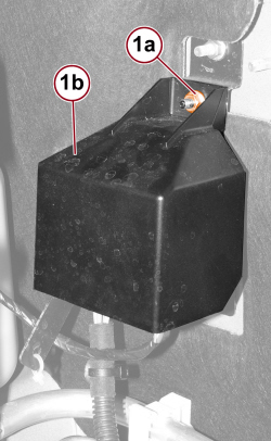 |
1. Undo the nut (1a) and remove the heater plugs control unit cover (1b). |
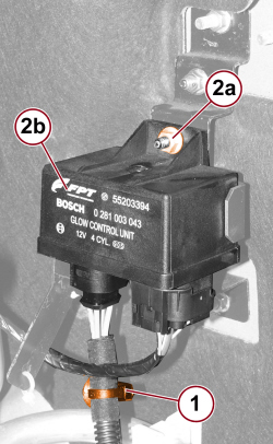 |
1. Release the wiring retaining band. 2. Undo the nut (2a) fixing the heater plugs control unit (2b). |
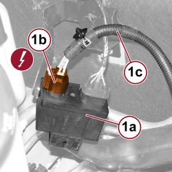 |
1. Turn the control unit (1a) upside down, disconnect the electrical connection (1b) and move the heater plugs wiring (1c) to one side.
|
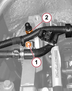 |
1. Undo the screw fixing the degassing pipe mounting bracket. 2. Undo the wiring mounting bracket fastener and move it to one side. |
|
|
|
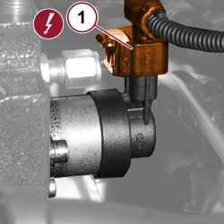 |
1. Disconnect the electrical connection for the fuel pressure regulator.
|
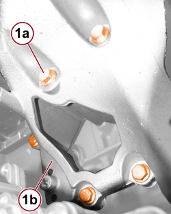 |
1. Undo the screws (1a) fixing the pressure pump mounting (1b) to the crankcase. |
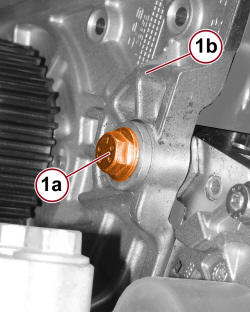 |
1. Undo the screw (1a) fixing the pressure pump mounting (1b) to the cylinder head and remove the mounting with pressure pump. |
|
|
- Separate the pressure pump from the mounting, with reference to Op. 1060E42 PRESSURE PUMP SUPPORT - DISMANTLING AND REASSEMBLY AT THE BENCH |
|
|
|
Refitting
(
Removing
)
- Fit the pressure pump on the mounting, with reference to Op. 1060E42 PRESSURE PUMP SUPPORT - DISMANTLING AND REASSEMBLY AT THE BENCH |
|
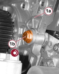 |
1. Place the pressure pump mounting (1a) back in position and tighten the camshaft housing fixing screw (1b) to the prescribed torque.
|
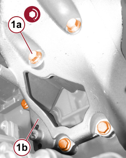 |
1. Tighten the screws (1a) fixing the pressure pump mounting (1b) to the crankcase to the prescribed torque.
|
|
|
- Connect the electrical connection for the fuel pressure regulator.
|
|
- Tighten the wiring mounting bracket fastener. - Tighten the screw fixing the degassing pipe mounting bracket. - Connect the electrical connection for the heater plugs control unit.
- Tighten the nut fixing the heater plugs control unit. - Engage the wiring retaining band. - Fit the heater plugs control unit cover and tighten the nut. |
|
|
Op. 1040B28 DUPLEX FUEL SUPPLY/RETURN PIPE TO PRESSURE PUMP - R.R. |
|
- Position a hydraulic lift under the engine. - Remove the timing side flexible mounting by undoing the engine mounting fixing screws and the body fixing nuts. - Remove the engine mounting by undoing the fixing screws. |
|
|
Op. 1032B10 TOOTHED TIMING BELT - R.R. FOR TIMING OR REPLACEMENT |
|
|
|
Op. 1008B10 POWER UNIT FRONT SUPPORT FLEXIBLE MOUNTING (TIMING SIDE) - REPLACE |
|
|
Op. 1048A42 SLEEVE FROM FLOW METER TO TURBO CHARGER AIR INLET PIPE - R + R |
|
|
|
|
Op. 1064B30 WASTEGATE SOLENOID VALVE MOUNTING BRACKET - R.R. |
|
Op. 1064B44 WASTE GATE VALVE ACTIVATION SOLENOID VALVE - R.R. |
|
Op. 1064B36 PRESSURIZED AIR SUPPLY PIPE TO WASTE GATE ACTUATOR - R.R. |
|
Op. 1064B35 PRESSURIZED AIR SUPPLY PIPE TO WASTE GATE VALVE - R.R. |
|
|
|
Op. 1092G15 ENGINE COMPONENT SINGLE BELT MOVING TENSIONER - R.R. WITH BELT REMOVED |
|
|
|
Op. 7055B56 Op. 7055B51 Op. 7055B91 |
|
- Connect the negative battery terminal.
Op. 5530B54 - Remove the vehicle from the lift. |