GENERAL INFORMATION
The vehicle is equipped with an electronic control system that governs the activation of specific containment devices in the event of a serious impact.
The protection system includes:
-
Airbag control unit;
-
Front belts with pretensioners and load limiters;
-
SBR function;
-
Driver's front airbag;
-
Front passenger airbag;
-
Two window bags, driver and passenger;
-
Two side bags, integrated in the front seats;
-
Two side impact detection sensors;
-
Passenger airbag disabling function.
The following indications show the system is working properly:
-
(red) fault warning light in the instrument panel;
-
passenger airbag disabled warning light in the instrument panel
-
connection via B- CAN with the diagnostic socket - integral with the Body Computer - to test operation via the EXAMINER.
The composition of the AIRBAG system is shown, in detail, in the figure below.
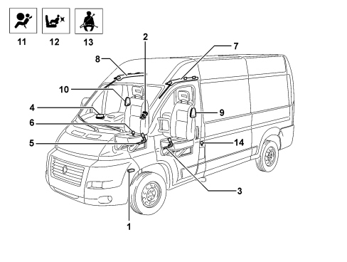
1 - Electronic control unit
2 - Driver's airbag module
3 - Driver's pretensioner
4 - Passenger side airbag module
5 - Passenger side pretensioner
6 - Passenger side impact sensor
7 - Driver's window bag module
8 - Passenger window bag module
9 - Driver's side bag module
10 - Passenger side bag module
11 - Airbag system fault indication warning light
12 - Passenger side front airbag deactivation warning light
13 - SBR warning light
14 - Driver's side impact sensor

|
The Safety Retention Systems are specifically designed to work on a given vehicle. They cannot therefore be tampered with, adapted or installed on other types of vehicle, but only those for which they have been designed and produced. Any attempt to reuse, adapt or install the system on a different type of vehicle could result in serious injury or even be fatal for the occupants of the vehicle both during normal usage and in the case of an accident.
|
|
|
For safety reasons, NO continuity checks can be carried out on the wiring.
|
AIR BAG ECU
The control unit is connected to the vehicle's electrical system via two connectors, one for the dashboard lead and the other for the cab lead.
The control unit is a B-CAN node and allows the exchange of information with the other nodes, in particular:
-
connection to the standard diagnosis socket via CAN;
-
to the instrument panel for operating the warning lights;
-
connection to the panel for a series of warnings if the belts are not fastened;
-
connection to the Body Computer for potential end of line customisation (Proxi), with a consequent reduction in the number of spare parts.
The following diagram shows the control unit.
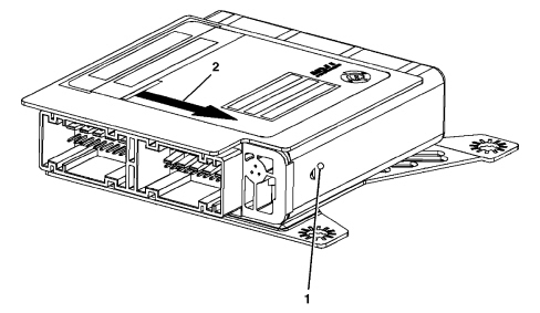
1 - Electronic control unit;
2 - Indication showing direction of motion.
The control unit is the central processing unit of the occupant protection system and is rigidly secured to the front tunnel.
It manages the retention system detection and activation devices, processing both the signals from the sensors installed inside and those which come from the side satellite sensors.

|
The control unit should always be fitted with the arrow 2, stamped on the adhesive plate, facing the direction of travel of the vehicle. Always check that there are no foreign bodies between the control unit and the body and tighten the bolts to the recommended torque.
|
The control unit contains an electronic deceleration sensor that enables safety device activation, this sensor consists of bi-directional accelerometers.

|
If the control unit falls to the ground or is subject to abnormal knocks during handling, it MUST be replaced.
|
After each activation of one of the controlled systems (pretensioners, front airbags), the control unit stores the activation in its permanent memory and controls activation of the fault warning light on the instrument panel.
Before it is replaced, the control unit guarantees activation of individual devices within the following limits:
-
3 impacts with activation only of the front seatbelt pretensioners;
-
1 knock with activation of pretensioners and front airbags;
-
any combination of the above-mentioned cases until the maximum number has been reached.
If one of the limits described is not reached, it will be possible to reuse the control unit after carrying out the RESET procedure using the EXAMINER once system operating conditions have been restored. The final activation, corresponding to the maximum number for the limits indicated, will prevent further reset procedures.
Pin out
The control unit connectors are illustrated in the figure below.
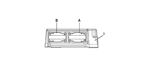
1 - Electronic control unit;
A - CONNECTOR A (cab wiring);
B - CONNECTOR B (dashboard wiring);
The connectors for the airbag control unit (NAB) are different depending on whether or not the passenger various optional airbags are present (passenger side, window bags and side bags).
This is necessary to prevent fitting an incorrect control unit from the Parts Dept. (foolproof logic).
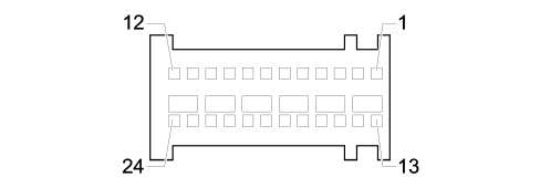
Connector A (CAB wiring)
|
1 |
NC |
|
2 |
NC |
|
3 |
NC |
|
4 |
NC |
|
5 |
DRIVER'S SEAT BELT NOT FASTENED SWITCH (EARTH) |
|
6 |
NC |
|
7 |
NC |
|
8 |
NC |
|
9 |
NC |
|
10 |
DRIVER'S SEAT BELT NOT FASTENED SWITCH (SIGNAL) |
|
11 |
NC |
|
12 |
NC |
|
13 |
CENTRE PRETENSIONER (-) |
|
14 |
CENTRE PRETENSIONER (+) |
|
15 |
NC |
|
16 |
NC |
|
17 |
NC |
|
18 |
NC |
|
19 |
NC |
|
20 |
NC |
|
21 |
PASSENGER PRETENSIONER (-) |
|
22 |
PASSENGER PRETENSIONER (+) |
|
23 |
DRIVER'S PRETENSIONER (+) |
|
24 |
DRIVER'S PRETENSIONER (-) |
Connector A (CAB wiring, FULL version)
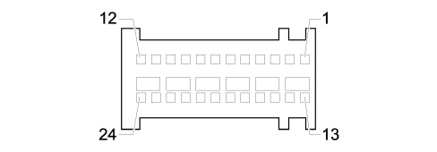
|
1 |
RIGHT SIDE IMPACT SENSOR (SIGNAL) |
|
2 |
LEFT SIDE IMPACT SENSOR (SIGNAL) |
|
3 |
RIGHT SIDE IMPACT SENSOR (EARTH) |
|
4 |
LEFT SIDE IMPACT SENSOR (EARTH) |
|
5 |
DRIVER'S SEAT BELT NOT FASTENED SWITCH (EARTH) |
|
6 |
NC |
|
7 |
NC |
|
8 |
NC |
|
9 |
NC |
|
10 |
DRIVER'S SEAT BELT NOT FASTENED SWITCH (SIGNAL) |
|
11 |
NC |
|
12 |
NC |
|
13 |
PASSENGER SIDE BAG (-) |
|
14 |
PASSENGER SIDE BAG (+) |
|
15 |
DRIVER'S SIDE BAG (+) |
|
16 |
DRIVER'S SIDE BAG (-) |
|
17 |
PASSENGER HEAD BAG (-) |
|
18 |
PASSENGER HEAD BAG (+) |
|
19 |
DRIVER'S HEAD BAG (+) |
|
20 |
DRIVER'S HEAD BAG (-) |
|
21 |
PASSENGER PRETENSIONER (-) |
|
22 |
PASSENGER PRETENSIONER (+) |
|
23 |
DRIVER'S PRETENSIONER (+) |
|
24 |
DRIVER'S PRETENSIONER (-) |
Connector B (DASHBOARD with passenger airbag wiring)
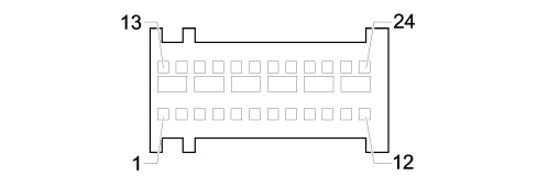
|
1 |
EARTH |
|
2 |
CONTROL UNIT IGNITION-OPERATED POWER SUPPLY FROM F50 CPL |
|
3 |
NC |
|
4 |
NC |
|
5 |
NC |
|
6 |
NC |
|
7 |
CAN-A B LINE |
|
8 |
CAN-B B LINE |
|
9 |
NC |
|
10 |
NC |
|
11 |
NC |
|
12 |
NC |
|
13 |
NC |
|
14 |
NC |
|
15 |
NC |
|
16 |
NC |
|
17 |
NC |
|
18 |
NC |
|
19 |
NC |
|
20 |
NC |
|
21 |
DRIVER'S SIDE FRONT BAG (-) |
|
22 |
DRIVER'S SIDE FRONT BAG (+) |
|
23 |
PASSENGER FRONT BAG (+) |
|
24 |
PASSENGER FRONT BAG (-) |
Connector B (DASHBOARD without passenger airbag wiring)
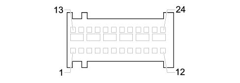
|
1 |
EARTH |
|
2 |
CONTROL UNIT IGNITION-OPERATED POWER SUPPLY FROM F50 CPL |
|
3 |
NC |
|
4 |
NC |
|
5 |
NC |
|
6 |
NC |
|
7 |
CAN-A B LINE |
|
8 |
CAN-B B LINE |
|
9 |
NC |
|
10 |
NC |
|
11 |
NC |
|
12 |
NC |
|
13 |
NC |
|
14 |
NC |
|
15 |
NC |
|
16 |
NC |
|
17 |
NC |
|
18 |
NC |
|
19 |
NC |
|
20 |
NC |
|
21 |
DRIVER'S SIDE FRONT BAG (-) |
|
22 |
DRIVER'S SIDE FRONT BAG (+) |
|
23 |
NC |
|
24 |
NC |
SELF-DIAGNOSIS
The control unit carries out continuous self-diagnosis of system operation. Specifically:
-
it diagnoses connections to system components and any type of fault that has occurred;
-
it detects and memorises any faults;
-
it indicates the source of these faults by turning on a warning light on the instrument panel.
Faults stored in the control unit may be deleted only after the fault has been repaired by means of the EXAMINER device.
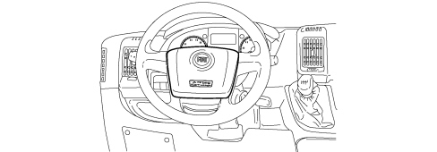
DRIVER'S FRONT AIRBAG
The location of the driver's airbag is illustrated in the figure below.
Specifications
The driver's airbag is a safety device. It takes the form of a bag that inflates in the case of a serious frontal impact to place itself between the driver's body and front passenger compartment structures. The airbag module is fitted in the centre of the steering wheel.
|
|
The failure of the airbag to activate in various types of non frontal impacts (side impact, rear impact, overturning, etc.) does not indicate a system malfunction.
|
The driver's airbag has a single activation stage: with medium-high severity impact the electronic control unit activates the airbag.
Straight after the impact and activation, once the retention function has been performed, the bag deflates through an opening in the lower part of the bag.
The view of the assembly is illustrated in the figure below.
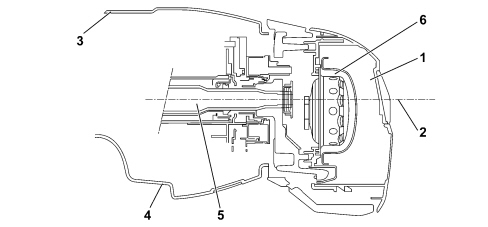
1 – Airbag
2 – Steering wheel axis
3 – Upper cover
4 – Lower cover
5 – Steering column
6 – Clock spring
Composition
The module comprises:
-
a plastic cover that tears at preset points when activated to allow the bag to expand correctly;
-
a 60 litre bag, made out of nylon thread woven to minimise skin abrasions in the case of contact and folded in such a way as to ensure that inflation is gradual and not directed toward the driver;
-
a gas generator;
-
a containment case.
|
|
Do not apply stickers or other objects to the steering wheel because they could interfere with the correct opening of the airbag and cause serious injury to the occupants of the vehicle.
|
FRONT AIRBAG PASSENGER'S SIDE
Specifications
The passenger airbag module is a passive safety device that protects the front passenger in the event of front impact by means of a bag that inflates and places itself between the occupant and the vehicle dashboard.
Bag inflation opens the flap on the dashboard along predefined cut lines. When fully inflated, the bag is in an optimal position to protect the occupant or, in case there is a two-seater bench, the occupants.
The airbag inflation methods has been designed in such a way as to avoid damaging collateral effects for the passengers.
The bag deflates immediately after the impact thanks to the presence of openings designed for this purpose.
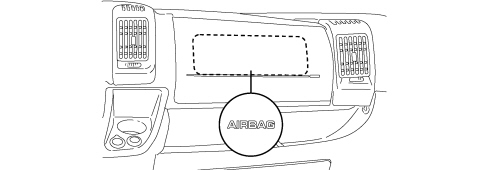
The location of the passenger airbag is illustrated in the figure below
Composition
The module comprises:
-
a metal containment mounting;
-
a bag protection that opens along predefined tear marks in the event of activation to allow the bag to emerge;
-
a 120 litre bag in nylon, a fabric that minimises skin abrasions in the event of contact. The bag is folded so that it does not inflate directly towards the occupant;
-
a gas generator;
-
mounting brackets on the crossmember.
The composition of the passenger airbag module is illustrated in detail in the figure below.
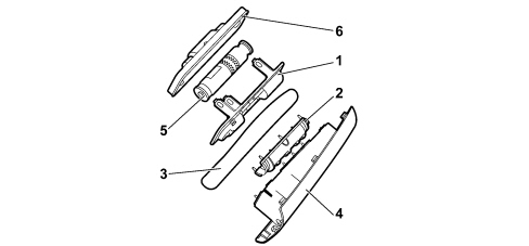
1 – Generator mounting
2 – Cover fastening plate
3 – Cover axes
4 – Cover
5 – Gas generator
6 – Safety plate
|
|
The failure of the airbag to activate in various types of non frontal impacts (side impact, rear impact, overturning, etc.) does not indicate a system malfunction.
|
|
|
Do not apply stickers or other objects to the passenger airbag cover, nor place any objects on the passenger dashboard because they could interfere with the correct opening of the airbag and cause serious injury to the occupants of the vehicle.
|
SIDE AIRBAG MODULE
Specifications
To increase the level of protection offered by the body in the event of a side impact, two Side Bag modules have been provided in the front seats.
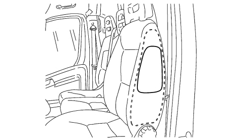
This device ensures the air bag is always in an optimum position in relation to the occupant, regardless of the angle of the seat or the size of the occupant.
The side bag protects the chest and pelvis areas and also - together with the door panels - protects critical areas of the body such as the ribs and abdomen.
|
|
Do not cover the front seat backrest with extra covers.
|
|
|
Do not wash the backrest with water or steam under pressure.
|
Composition
The side bag module consists of a metal container that houses the gas generator and a nylon bag with a volume of about 10 litres.
The plastic container includes a bag protection with preset break points. When the backrest cover is fitted, the exterior of the trim in the area over the bags, includes seams designed to yield easily to allow the bag to inflate.
Operation
The gas generator is activated electrically by means of a signal coming from the electronic control unit which detects the impact through data communication from the side sensors. Following this signal, pyrotechnic activation is triggered, causing the gas in the generator to expand.
The gases expand and emerge through openings to inflate the bag. The bag's deployment causes the seams designed to yield easily on the backrest cover to yield, allowing the bag to open correctly.
When fully inflated, the bag is in an optimum position to protect the occupant.
Deflation is immediate due to the presence of a vent hole.
|
|
It is not possible to carry out operations on seats fitted with air bags, apart from seat removing-refitting. It is strictly forbidden to disassemble seats fitted with airbags.
|
|
|
Non-activation of side bags in other types of collisions (front collisions, rear shunts, roll-overs, etc.) is not a system malfunction.
|
SIDE WINDOW AIRBAG MODULE
Specifications
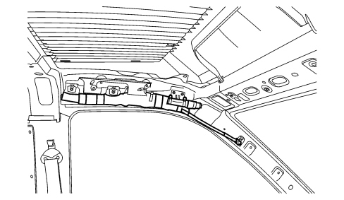
They consist of two curtain bags, one on the right and the other on the left side of the vehicle, located behind the side coverings of the roof and covered by special finishing.
Window bags have been designed for protecting the head of front occupants in the event of side impact, thanks to the wide bag inflation surface.
Composition
The window bag module consists of:
-
a gas generator secured by appropriate mountings to the side pillar of the vehicle;
-
a flexible pipe in permeable fabric secured by a band to the gas generator, which diffuses the gas evenly over the entire length of the bag
-
a bag of about 30 litres in volume secured to the gas generator together with a flexible pipe. It is made out of permeable nylon and is folded inside a containment sleeve. The bag is designed to ensure, once fully inflated, correct absorption of impact energy while maintaining the occupants' heads at a proper distance from the impact area.Once fully inflated, the gas leaves the bag immediately through the porous fabric.
-
plastic clips and metal supports that secure the bag to the ceiling rail;
-
a retaining belt secured to the front pillar that holds the bag in position once inflated.
Operation
The gas generator is electrically activated by means of a signal from the electronic control unit. Following this signal, pyrotechnic activation is triggered, causing the gas in the generator to expand. The expanding gas emerges through special openings and is distributed evenly along the length of the bag through the hose to make the bag inflate. The increase in the bag volume causes the container to break, the stitching to yield and the opening of the trim thereby allowing the bag to come out correctly downwards. The bag is made to inflate correctly by a retaining strap on the front end of the bag. When fully inflated, the bag is in an optimum position to protect the occupant. The bag deflates immediately after being inflated by the gas because the fabric is permeable.
FRONT SEAT BELTS WITH PRETENSIONERS AND LOAD LIMITERS
Specifications
The seat belt pretensioner is a pyrotechnic device incorporated in the buckle which attaches to the belt.
In the case of a serious frontal impact, the pretensioner intervenes recovering the inevitable lengthening of the belt due to the action of the weight of the body which is kept as close as possible to the seat.
If the belt remains close to the body, it can gradually absorb the kinetic energy produced during the impact.
The driver's pretensioner, incorporating the seat belt not fastened switch is illustrated in the figure below.
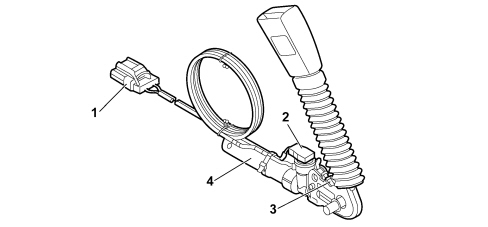
1 – Section with vehicle wiring
2 – Pretensioner connection
3 – Seat belt switch (only present on driver's side)
4 – Pretensioner device
The passenger side pretensioners, both on the version with a single seat and the one with a two-seater bench (where there are two devices), are identical to the ones on the driver's side with the exception of the fact that there is no switch for detecting whether the seat belt is fastened.
Operation
Having detected the conditions for activating the seat belt pretensioning system, the airbag control unit activates the pretensioner.
The gas pressure developed inside the device presses the surface of an integrated piston, pushing it inside its housing.
The piston is connected, by a cable, to the end of the belt mounting.
The movement of the piston drives the buckle downwards, shortening the belt by a few centimetres recovering the lengthening and any slack.
After activation the pretensioner stops operating and cannot, under any circumstances, be repaired.
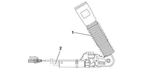
1 – Belt buckle retraction area
2 – Piston projection area
All the seat belts are also fitted with load limiters which decrease the force transmitted by the belts to the chest: the force level at which the limiters act is sufficient to considerably reduce the risk of fracturing shoulder blades and ribs, even in people with brittle bones (e.g. the elderly).
|
|
The pretensioner intervention levels are lower than those for airbags, which means that impacts in which only the pretensioner intervenes can take place.
|
|
|
Pretensioners can only be used once; they must be replaced once they have been activated which can be seen by the retraction of the buckle downwards and the “airbag failure” warning light in the instrument panel coming on.
|
Sbr function (seat belt reminder)
The vehicle is equipped with a SBR (Seat Belt Reminder) system consisting of a buzzer that notifies the driver that his seat belt is unfastened, complemented by a flashing seat belt unfastened warning light on the instrument panel.
The operation is managed in different ways. In particular there is an "initial warning cycle" with a warning light only and a "warning cycle" with a buzzer as well inside the instrument panel.
"First warning cycle": signalling via warning light
The “seat belts” warning light signals that the driver's seat belt is not fastened in accordance with the following logic:
-
the warning light comes on in fixed mode, at key-ON, if the seat belt has not already been fastened;
-
the warning light comes on in fixed mode if, at key-ON, the belt is unfastened (unless the “warning cycle” conditions apply, then the warning light should flash);
-
the warning light remains off if the seat belt was already fastened at key-ON;
-
the warning light goes out at key-ON if the seat belt is fastened.
The warning light goes out, in any case, at key-OFF.
“Warning cycle”: indication via warning light + buzzer
The “warning cycle” is activated for 90 seconds if, with the seat belt not fastened and the key in the MAR-ON position, at least one of the following conditions is verified:
-
Time elapsed equal to 60 seconds and vehicle speed above 10 km/h;
-
Vehicle speed above 25 km/h;
-
Distance travelled more than 500 m.
This “warning cycle” involves:
-
“seat belts” warning light on flashing (frequency 2 Hz, D.C. 50%);
-
acoustic warning via buzzer in the instrument panel.
During the 90 second cycle:
-
if the seat belts are fastened, the warning cycle is immediately interrupted and the system is prepared for a new signalling;
-
if one of the events that caused the activation of the warning cycle no longer exists, the cycle continues until the 90 seconds have elapsed;
-
if a further warning is required, the control panel indicates the new event by interrupting the current warning cycle (the acoustic signal stops and the “seat belts not fastened” warning light changes from a flashing to a fixed light) and activating the new signal. The system then resumes the warning cycle prior to the new, most recent warning event. If the seat belt is fastened during the new event warning, the warning cycle ceases;
-
if a key-OFF is carried out, the warning cycle is immediately interrupted.
Later on, at the end of the 90 second cycle, if the seat belt is still not fastened:
Exclusion of the “warning cycle”
Temporary exclusion
The “warning cycle” can be temporarily deactivated through the following procedure.
Within one minute of key-ON, proceed as follows:
-
fasten the driver's seat belt (if it is already fastened at the key-ON the cycle will naturally not be started);
-
with the ignition key at MAR-ON, keep the seat belt fastened for at least 20 seconds;
-
unfasten the seat belt.
The warning cycle will be automatically activated again at each new key-ON operation.
Permanent exclusion
The warning cycle can be permanently deactivated using the diagnostic equipment.
After it has been permanently deactivated, there is a specific option in the set up menu that allows this function to be reactivated using the set up menu.
SIDE IMPACT SATELLITE SENSORS
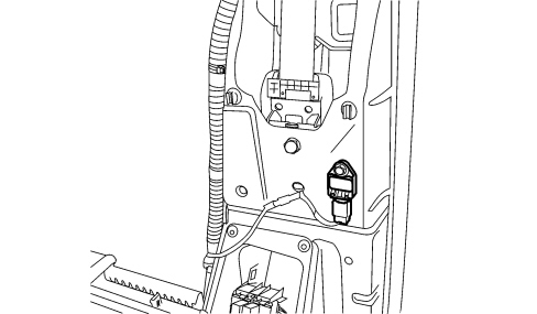
The location of the side impact sensor is shown below.
Specifications
The side protection system consists of the air bags and also an electronic control circuit that ensures the system operates correctly. Two satellite sensors containing an accelerometer are installed inside the side pillars to measure accelerations resulting from side impact.
Operation
If the acceleration level detected by the relevant sensor causes a given threshold to be exceeded, the information is compared with a measurement obtained by a safety sensor in the airbag system electronic control unit. If the values measured are consistent, the control unit controls the activation of the side bags and the windows on the side affected by the impact only.
PASSENGER AIRBAG DISABLING FUNCTION
The front passenger airbag module can be disabled by following the special procedure in the instrument panel menu.
|
|
GRAVE DANGER! The front passenger airbag module MUST BE ABSOLUTELY deactivated if a child seat is fitted to the front passenger seat.
|
The procedure differs depending on whether the vehicle has a digital display (Modal version) or a multifunction display (Comfort version).
Modale version
To activate / deactivate the passenger airbag, proceed as follows:
-
press the “MODE” button and, after the (BAG P OFF) message (for deactivation) or the (BAG P ON) message (for activation) is shown in the display, press the “MODE” button again using the “arrow” scroll buttons in the menu;
-
a confirmation request message will appear on the display;
-
by pressing the menu “arrow” scroll buttons select (YES) (to confirm the activation/deactivation) or (NO) (to abort);
-
press the “MODE” button briefly, a message confirming the selection will be displayed and you will return to the menu screen or pressing the button for longer you will return to the standard screen without saving.
Deactivation is indicated by a warning light in the instrument panel coming on.
Comfort version
To activate / deactivate the passenger airbag, proceed as follows:
-
press the “MODE” button and, after the (Bag pass: Off) message (for deactivation) or the (Bag pass: On) message (for activation) is shown in the display, press the “MODE” button again using the “arrow” scroll buttons in the menu;
-
the confirmation request message will appear on the display;
-
by pressing the menu “arrow” scroll buttons select (Yes) (to confirm the activation/deactivation) or (No) (to abort);
-
press the “MODE” button briefly, a message confirming the selection will be displayed and you will return to the menu screen or pressing the button for longer you will return to the standard screen without saving.
Deactivation is indicated by a warning light in the instrument panel coming on.
CLOCK SPRING
The clock spring is illustrated in the diagram.
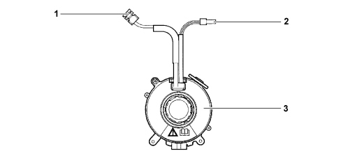
1 - Electrical connection for connecting airbag
2 - Steering wheel electrical function lead
3 - Clock spring
Specifications
The clock spring transfers the electrical signal to controls on the steering wheel (horn and other optional controls) and connects the air bag module without risk of breakage.
The device consists of two plates and is secured to the steering wheel interface via its lower plate.It is built into the steering wheel by means of fasteners on the upper plate. Inside the two plates, the leads connecting the module and horn buttons are wound in a coil so that they can follow steering wheel movements.
Pin out
|
1 |
STEERING WHEEL CONTROLS LIGHT EARTH |
|
2 |
REFERENCE EARTH FOR RADIO CONTROLS |
|
3 |
STEERING WHEEL CONTROLS (MUTE, VOL+, VOL-) |
|
4 |
STEERING WHEEL CONTROLS (SOURCE, SCAN+, SCAN-) |
|
5 |
STEERING WHEEL CONTROLS LIGHTING |
|
6 |
NC |
|
7 |
EARTH FOR HORN |
|
8 |
HORN SIGNAL |
|
9 |
DRIVER'S AIRBAG (+) |
|
10 |
DRIVER'S AIRBAG (-) |
|
11 |
NC |
|
12 |
NC |
Composition
The clock spring may have two or three connections on the steering wheel side depending on whether or not there are radio controls on the steering wheel.
A ring on the lower plate, steering wheel side, automatically prevents both plate from turning in relation to one another when the device is disconnected from the steering wheel.
The new clock spring is equipped with a safety key for transport, which must be removed after installation.
Operation
Inside the two plates, the leads connecting the airbag module and the various electrical functions are wound into a spiral with sufficient coils to follow the steering wheel rotations. The upper plate is turned by fasteners on the inside of the retaining ring that fit into the seat on the steering wheel hub. In working position, the steering wheel presses on the ring to release it from its fasteners, thus allowing rotation between the two plates. When the steering wheel is removed, the spring-loaded ring locks rotation between the two plates. This function prevents the upper plate, now no longer secured to the steering wheel, from turning freely and unwinding or winding the coil inside the device and possibly causing it to break.
In operations that require the removal of the steering wheel and the device it is compulsory to observe the following:
-
always work with wheels aligned in a straight driving position;
-
lock, for safety, the two discs with a band before removing the steering wheel interface device.
|
|
If the upper plate should turn in relation to the lower plate for any reason so that the exact starting position is no longer completely certain, the clock spring MUST BE ABSOLUTELY replaced.
|
AIRBAG WARNING LIGHTS
During starting, the fault warning light (red) comes on for about four seconds (initial self-diagnosis stage) and then goes off. If the control unit detects a fault in the warning light, it saves the corresponding fault code. If no system faults are detected at key on and no fault conditions are present in the fault memory, the warning light goes off after four seconds of self-diagnosis. Otherwise it stays on.
The warning light remains lit or comes on during driving in the following instances:
The failure of the airbag warning light (warning light off) is signalled by the flashing of the front passenger airbag disabled warning light for longer than the usual 4 seconds.
As a consequence of a crash when the pretensioners alone are activated, the warning light stays on until system operating conditions are restored (replacement of affected part or control unit repair using EXAMINER).
If the crash causes the front airbag modules to activate, the warning light stays on permanently because the control unit cannot be reset (in this case the control unit must be replaced).
If internal operating errors occur during the working life of the control unit that cannot be repaired with EXAMINER, these are indicated by permanent activation of the warning light.
The passenger airbag disabled warning light comes on when the airbag is deactivated and remains on constantly until it is reactivated.
|