





|
|






|
|
Service News
|
|
Copyright By FCA Italy S.p.A. - Printed 09/01/2015 – Esc.876
|
|
|
Ducato (250)
Version: all models
|
|
|
|
|
4410 1 541 MA
|
FRONT SHOCK ABSORBERS
Noise from the upper part while steering - Service Solution
|
|

|
Cancels and replaces SN 44.06.14 of 28.05.2014 for Part Availability table upgrade.
|
CLAIMED FAULT
Noise, coming from the front suspension upper part, that can be felt while steering at low speed also or when the vehicle is at a standstill.
|
|
If the noise occurs while driving on irregular road surfaces and only when the outside temperature is lower than 0°C, see Service News 44.07.13
|
TECHNICAL CAUSE
Inlet of foreign bodies (dust, water, mud, etc.) in the bearing inside the flexible buffers (thrust washers) of front shock absorber.
OPERATIONS AT THE DEALERSHIPS
DEALERSHIP BEHAVIOUR STANDARDS TOWARDS THE CUSTOMER
-
Once the customer's claimed fault is confirmed, reassure the customer that the problem will be solved by replacing the flexible buffers and upper laying rings for the springs with new ones, having improved features.
-
After the operation, show the Customer what has been done and make sure he is satisfied.
Service Solution
Once the customer's claimed fault is confirmed, replace the flexible buffers and the upper laying rings for the springs, according to the Operating Cycle below.
OPERATION CYCLE
The operations described must be performed on both front shock absorbers.
-
Position the vehicle on a lift.
-
Remove both front shock absorber units and separate them, see Op. 4410A12 of the Service Manual.
-
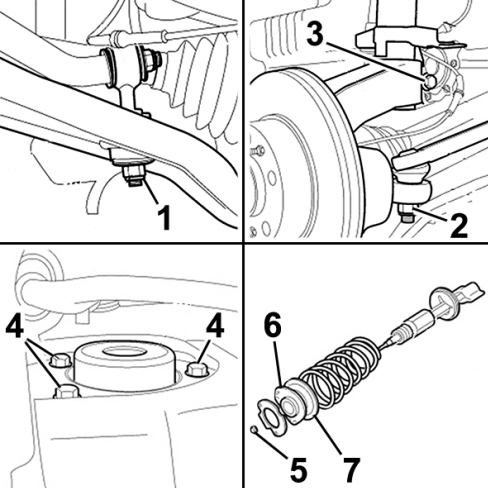
Replace the flexible buffers (6 – Fig.1) and the upper laying rings for the springs (7) with new ones, taken from the Spare Parts Dpt.

|
During refitting, always replace the removed self-locking nuts with new ones from the Spare Parts Dpt. and tighten to the prescribed torque, with reference to Op. 4410A12 in the Service Manual.
|
-
Reassemble the front shock absorbers units and refit them on the car, see Op. 4410A12 of the Service Manual.
-
Refit the other parts removed during disassembly, with reference to the Service Manual.
-
Check the front wheel geometry, with reference to Op. 4450A10 of the Service Manual.
Fig. 1
PARTS AVALABILITY
|
All models in question, versions with Optional 57A, 6SC excluded |
Shock absorber mounting kit |
1383656080 |
1 (a) |
|
All models in question, versions with Optional 57A, 6SC only |
Shock absorber mounting kit |
1383654080 |
1 (b) |
|
All models in question |
Nut M12x1.25 (re. 1) for anti-roll bar fastening to the wishbone |
15503811 |
2 (***) |
|
All models in question |
Nut M14x1.5 (re. 2) for steering rod fastening |
15503921 |
2 (*) |
|
All models in question, versions with Optional 57A, 6SC excluded |
Screw M12x1.25 x75 for the bolt (re. 3) fastening the shock absorber to the steering knuckle |
1348819080 |
2 (**) |
|
All models in question, versions with Optional 57A, 6SC only |
Screw M14x2x80 for the bolt (re. 3) fastening the shock absorber to the steering knuckle |
1360106080 |
2 (*) |
|
All models in question, versions with Optional 57A, 6SC excluded |
Nut M12x1.25 for the bolt (re. 3) fastening the shock absorber to the steering knuckle |
12578421 |
2 (*) |
|
All models in question, versions with Optional 57A, 6SC only |
Nut M14x2 for the bolt (re. 3) fastening the shock absorber to the steering knuckle |
1360107080 |
2 (****) |
|
All models in question |
Nut M14x1.5 (re. 5) for shock absorber fastening to the flexible mounting |
50706275 |
2 (*) |
Optional 57A = Egyptian Market
Optional 6SC = Demanding roads
(a) Kit 1383656080 includes the following components:
-
51778629 - Screw M10x1.25x35 (re. 4 - Fig. 1) for shock absorber fastening to the turret
-
1374666080 - Left flexible mounting (re. 6 – Fig. 1)
-
1374667080 - Right flexible mounting (re. 6 – Fig. 1)
-
1376670080 - Upper laying ring for springs (re. 7 - Fig. 1)
(b) Kit 1383654080 includes the following components:
-
51778629 - Screw M10x1.25x35 (re. 4 - Fig. 1) for shock absorber fastening to the turret
-
1375165080 - Left flexible mounting (re. 6 – Fig. 1)
-
1375164080 - Right flexible mounting (re. 6 – Fig. 1)
-
1376670080 - Upper laying ring for springs (re. 7 - Fig. 1)
(*) The pack contains 5 components
(**) The pack contains 6 components
(***) The pack contains 8 components
(****) The pack contains 10 components
CLAIM REPORT DATA
|
All models in question |
4410154 |
1 |
MA |
010-090 |
3.30 (*) |
(*) the time allowance includes replacing of flexible buffers and upper laying rings for the springs for both shock absorbers plus front wheel geometry adjustment
|