
 |
- This check procedure must be carried out after each operation on the front suspension mechanical components since their purpose is to define the position of the wheels in relation to the body (e.g.: wishbones, steering knuckles, shock absorbers, springs, etc.). OPERATING CYCLE Introduction - The wheel angle/geometry checks should be carried out using the appropriate optical equipment. - Before checking the wheel angles/geometry, the following checks must be carried out: - tyre inflation pressure within the prescribed figures; - eccentricity and orthogonality of the wheel rims which should not be more than 3 mm; - wheel bearing endfloat; - clearance between the steering knuckle and wishbone ball pin; - steering rod ball pin clearance. - Let the suspension bed in driving the vehicle over an uneven surface. - Make sure that the vehicle complies with the following load condition: - "Standard A" vehicle "unladen" - this is the weight of the complete vehicle, including spare wheel, tools, accessories, supplies (full fuel tank). CHECKING AND ADJUSTING FRONT SUSPENSION GEOMETRY/ANGLES Camber check
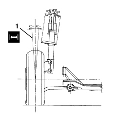
1. Check that the front wheel camber is within the prescribed limits (only to be checked as a percentage).
|
||||||||

 |
Caster check
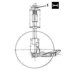
1. Check that the front wheel caster is within the prescribed limits (only to be checked as a percentage).
|
||||||||
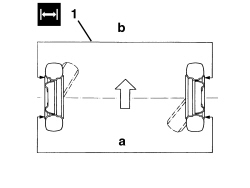 |
Front wheel toe-in check 1. Measure the distance "b", on a horizontal plane passing through the wheel centres, between the 2 outer front points of the wheel rims, then rotate the rims through 180° and measure the distance "a" between the same points. The toe-in should be within the prescribed values.
|
||||||||||||||
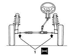 |
1. If the front wheel toe-in value measured is different from the prescribed value, work symmetrically on the steering rods, after having loosened the fixing nuts and observing the following warnings.
|
