|
1 |
Check using diagnosis equipment Connect the diagnosis equipment to the Powertrain Control Module and check that the signal for track 1 in rest position is between 900 and 1100 mV |
Check/Restore the correct wiring connections. If the value remains out of range go to Step 5. |
|
2 |
Check using diagnosis equipment Keeping the diagnosis equipment connected to the Powertrain Control Module, check that the signal for track 2 in rest position is between 350 and 650 mV. |
Check/Restore the correct wiring connections. If the value remains out of range go to Step 5. |
|
3 |
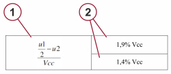
Check using diagnosis equipment Keeping the diagnosis equipment connected, check that the track 1 and track 2 signals in rest position are consistent with each other, calculating the interlinearity and checking that the values are acceptable as indicated in Figure 1 (max = 1.4% Vcc). |
Check/Restore the correct wiring connections. If there is no correlation between track 1 and track 2 go to Step 5. |
|
4 |
Check using diagnosis equipment Connect the diagnosis equipment and check that the track 1 and track 2 signals in end of travel position are consistent with each other, calculating the interlinearity and checking that the values are acceptable as indicated in Figure 1 (max 1 = 1.4% Vcc). End of diagnosis |
Check/Restore the correct wiring connections. If there is no correlation between track 1 and track 2 go to Step 5. |
|
5 |
Check the operation of the accelerator pedal Keeping the diagnosis equipment connected, check that the accelerator pedal is operating correctly. |
Accelerator pedal not operating correctly, replace it. Op. 1068A20 ACCELERATOR PEDAL WITH BUILT-IN POTENTIOMETER - R.R |
1. Formula (u1= track 1 signal, u2= track 2 signal)
2. Max. value