1004D10 POWER UNIT (MANUAL GEARBOX), REMOVED, DISMANTLE AND REASSEMBLE

|
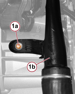
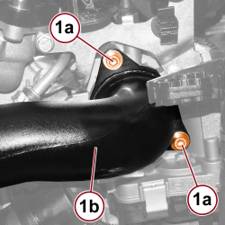
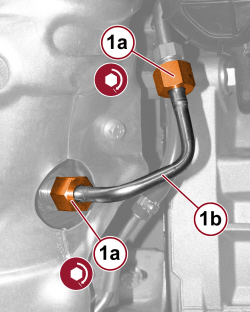
1. Undo the fixing screws (1a), disconnect the pipe (1b) and remove it.
|
|
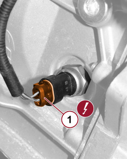
1. Disconnect the electrical connection for the reversing light switch.
|
1 |
Reversing light switch |
See I020 |
|
|
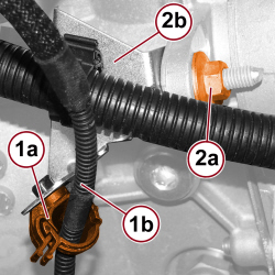
1. Open the retaining clip (1a) and release the reversing light switch wiring (1b).
2. Undo the bolt (2a) and free the wiring mounting bracket (2b).
|
|
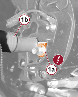
1. Undo the nut (1a) and disconnect the alternator supply lead (1b).
|
|
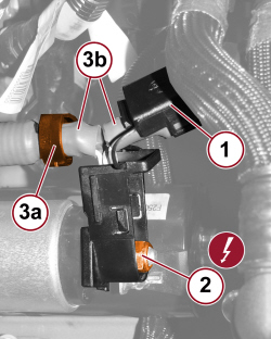
1. Open the protective cover.
2. Undo the nut and disconnect the alternator and starter supply lead.
3. Open the retaining clip (3a) and remove the alternator and starter supply lead (3b).
|
|
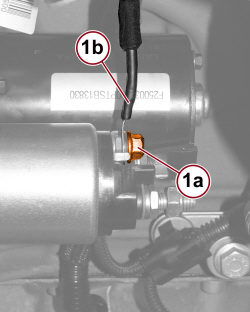
1. Undo the nut (1a) and disconnect the starter triggering lead (1b).
|
|
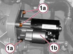
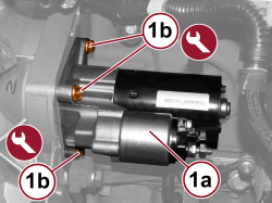
1. Undo the fixing screws (1a) and remove the starter (1b).
|
|
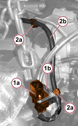
1. Release the oxygen sensor connector (1a) from the mounting bracket (1b).
2. Open the retaining clips (2a) and release the oxygen sensor wiring (2b).
|
|
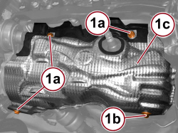
1. Undo the screws (1a) and the nuts (1b) and remove turbocharger heat shield (1c).

|
When removing the heat shield, be careful not to damage the oxygen sensor wiring.
|
|
|
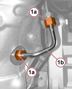
1. Undo the connectors (1a) and remove the pressure intake pipe (1b) upstream of the particulate filter.
|
|
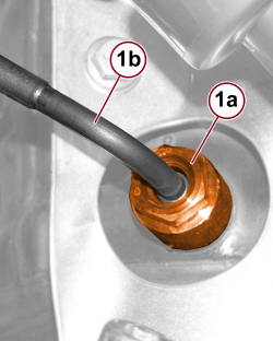
1. Undo the connector (1a) and remove the exhaust gas temperature sensor (1b).
|
|
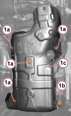
1. Undo the screws (1a) and the nuts (1b) and remove turbocharger heat shield (1c).
|
|
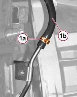
1. Undo the band (1a) and disconnect the pressure intake pipe (1b) downstream of the particulate filter.
|
|
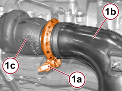
1. Undo the nut (1a) for the collar fixing the particulate filter (1b) to the turbocharger (1c).
|
|
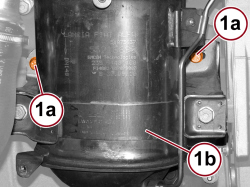
1. Undo the screws (1a) fixing the mounting bracket to the crankcase and remove the particulate filter (1b).
|
|
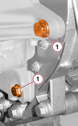
1. Undo the front gearbox fixing screws.
|
|
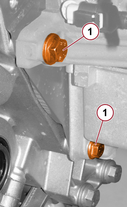
1. Undo the rear gearbox fixing screws.
|
|
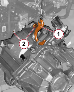
1. Prepare a hydraulic lift and a suitable hook to support the gearbox.
2 . Undo the upper gearbox fixing screws.
|
|
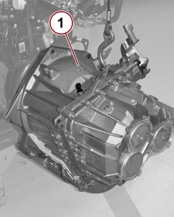
1. Remove the gearbox separating it from the engine.
|
|
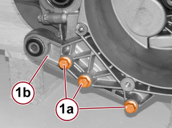
1. Undo the fixing screws (1a) and remove the reaction bracket (1b).
|
|
 Refitting
(
Removing Refitting
(
Removing )
)
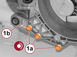
1. Tighten the screws (1a) fixing the reaction bracket (1b) to gearbox to the prescribed torque. |
|
Gearbox bracket for lower reaction rod |
Screw |
M12 |
10.0 ÷ 11.0 |
2.0 JTD 115 HP |
|
|
|
- Place the gearbox in position on the engine and tighten the fixing screws.
- Remove the hook and the hydraulic lift used to support the gearbox.
|
|
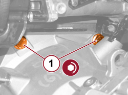
1. Tighten the upper gearbox fixing screws to the prescribed torque.
|
Gearbox to engine |
Screw |
M12x1.25x68 |
5.9 ÷ 7.2 |
2.0 JTD 115 HP |
|
|
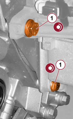
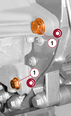
1. Tighten the rear gearbox fixing screws to the prescribed torque.
|
Gearbox to engine |
Screw |
M12x1.25x68 |
5.9 ÷ 7.2 |
2.0 JTD 115 HP |
|
Gearbox to engine |
Screw |
M10x1.25x60 |
3.6 ÷ 4.4 |
2.0 JTD 115 HP |
|
|
1. Tighten the front gearbox fixing screws to the prescribed torque.
|
Gearbox to engine |
Screw |
M12x1.25x68 |
5.9 ÷ 7.2 |
2.0 JTD 115 HP |
|
Gearbox to engine |
Screw |
M10x1.25x60 |
3.6 ÷ 4.4 |
2.0 JTD 115 HP |
|
|
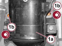
1. Position the particulate filter (1a) in its housing and tighten the mounting bracket fixing screws (1b) to the prescribed torque.
|
Particulate filter (DPF) mounting bracket |
Screw |
M8 |
2.3 ÷ 2.8 |
2.0 JTD 115 HP |
|
|
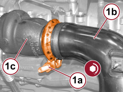
1. Tighten the nut (1a) for the collar fixing the particulate filter (1b) to the turbocharger (1c) to the prescribed torque.
|
Turbocharger side particulate filter (DPF) |
Collar nut |
M10 |
2.2 ÷ 2.6 |
2.0 JTD 115 HP |
|
|
|
- Connect the pressure intake pipe downstream of the particulate filter and close the band.
- Fit the particulate filter heat shield in position and tighten the fixing screws and nuts.
|
|
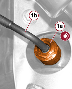
1. Tighten the connector (1a) for the exhaust gas temperature sensor (1b) to the prescribed torque.
|
Exhaust gas temperature sensor on particle filter |
Connector |
M14 |
4.0 ÷ 5.0 |
2.0 JTD 115 HP |
|
|
1. Tighten the connectors (1a) for the pressure intake pipe (1b) upstream of the particulate filter.
|
|
|
- Fit the turbocharger heat shield in position and tighten the fixing screws and nuts.
- Place the oxygen sensor in position on the mounting bracket, engage the wiring and close the retaining clips.
|
|
1. - Place the starter (1a) in position and tighten the fixing screws (1b) to the prescribed torque.
|
Starter motor |
Screw |
|
|
2.0 JTD 115 HP |
|
|
|
- Connect the starter triggering lead and tighten the fixing nut.
- Place the alternator and starter supply cable in position and close the retaining clip.
- Connect the starter supply cable and tighten the fixing nut.
- Connect the supply lead to the alternator and tighten the fixing nut.
- Tighten the wiring mounting bracket fixing bolt to the prescribed torque.
|
Supply cable mounting bracket on gearbox bell housing |
Screw |
M8 |
1.2 ÷ 1.8 |
2.0 JTD 115 HP |
- Engage the reversing light switch wiring and close the retaining clip.
- Connect the electrical connector for the reverse light switch.
|
- |
REVERSING LIGHT SWITCH |
See I020 |
- Undo the screws fixing the pipe to the throttle casing.
- Tighten the screw for the bracket fixing the pipe to the crankcase.
|