2110B32 MANUAL GEARBOX (5 SPEED) WITH DIFFERENTIAL - DISMANTLING AND REASSEMBLY - WASH AND CHECK PARTS - REPLACE SYNCHRONISERS, INNER CONTROLS, GEARS, SHAFTS AND BEARINGS

|
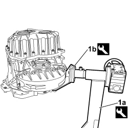
1. Position the gearbox on the rotating stand (1a) using the support (1b).
|
1.871.000.000 |
Gearbox support rotating stand |
Gearbox fastening for dismantling |
2.0 JTD 115 HP |
|
1.871.001.014 |
Support for 1.871.000.000 |
Gearbox fastening for dismantling |
2.0 JTD 115 HP |
|
|
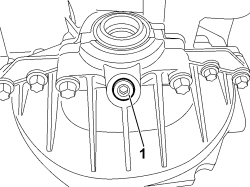
1. Undo the oil drain plug on the differential cover.
|
|
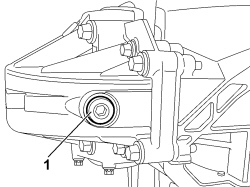
1. Undo the magnetic plug on the differential cover.
|
|
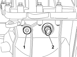
1. Undo the oil filler plug on the gearbox.
2. Undo and remove the reversing switch.
|
|
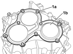
1. Undo the fixing screws (1a) and remove the rear cover (1b).
|
|
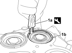
1. Use pliers (1a) to remove seeger ring (1b) from main shaft bearing.
|
1.870.492.000 |
Calliper |
Removing-refitting snap rings |
2.0 JTD 115 HP |
|
|
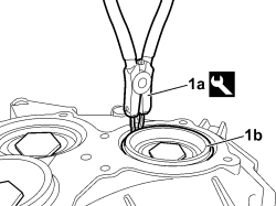
1. Use pliers (1a) to remove seeger ring (1b) from upper layshaft bearing.
|
1.870.492.000 |
Calliper |
Removing-refitting snap rings |
2.0 JTD 115 HP |
|
|
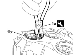
1. Use pliers (1a) to remove seeger ring (1b) from lower layshaft bearing.
|
1.870.492.000 |
Calliper |
Removing-refitting snap rings |
2.0 JTD 115 HP |
|
|
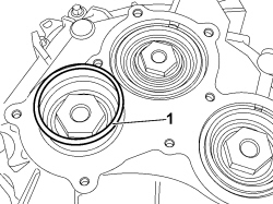
1. Remove the shim from the lower layshaft bearing.
|
|
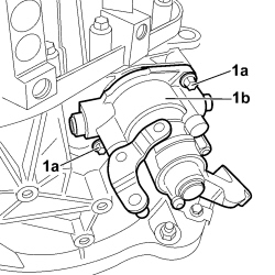
1. Undo the fixing screws (1a) and remove the gear selector/engagement mechanism (1b).
|
|
|
- Engage two gears.

|
The simultaneous engagement of two gears results in the gearbox shafts locking; this operation is necessary in order to be able to release the ring nuts securing the gears to the shafts.
|
|
|
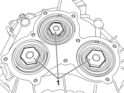
1. Undo the ring nuts securing the gears to the gearbox shafts.
|
|
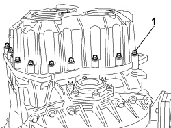
1. Loosen the fixing screws securing the gearbox gear casing.
|
|
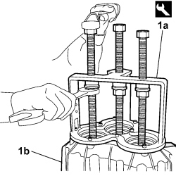
1. Remove the gearbox gear casing (1b) using the fitting/extraction tool (1a).
|
2.000.019.400 |
Extractor/fitting tool |
Gearbox casing separator/inserting tool kit |
2.0 JTD 115 HP |
|
|
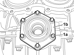
1. Undo the fixing screws (1a) and remove the flange (1b).
|
|
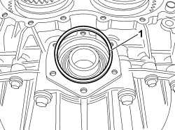
1. Remove the differential casing adjustment ring.
|
|
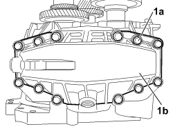
1. Undo bolts (1a) and remove differential cover (1b).
|
|
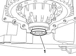
1. Remove the oil seal from the differential casing (clutch side).
|
|
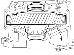
1. Remove the differential.
|
|
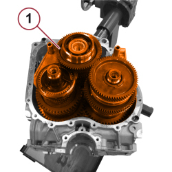
1. Extract from their seats the main shafts and layshafts complete with gears and gear selection levers with respective forks.
|
|
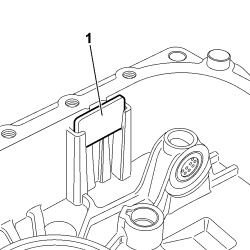
1. Extract the magnet from the seat and remove any metal particles that may be present.
|
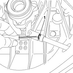
|
1. Undo the clip fastening the connector, between the pipe supplying the clutch and the clutch release sleeve, to the sleeve.
|
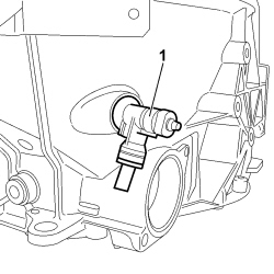
|
1. Remove the connector between the clutch supply pipe and the clutch release sleeve.
|
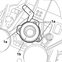
|
1. Undo the fixing screws (1a) and remove the clutch release sleeve (1b).
|
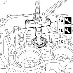
|
1. Using tools (1a) and (1b), remove the main shaft bearing (1c) from the gearbox mounting case.
|
|
Check that the outer race, inner race and rollers are free of scratches, overheating marks and excessive wear, and that the bearing rolls freely without catching. Replace the complete bearing if this is not the case.
|
|
Usag 468/1 |
Extractor |
Universal extractor |
2.0 JTD 115 HP |
|
Usag 468A/5 |
Extractor |
Removing main shaft bearing |
2.0 JTD 115 HP |
|
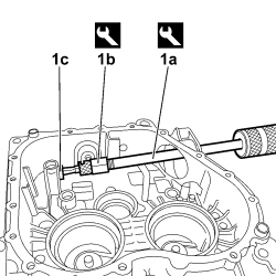
|
1. Using tools (1a) and (1b), remove the gear selection/engagement shaft bearing (1c).
|
|
Check that the bearing rolls freely and without impediment; if not, replace the entire bearing.
|
|
1.847.017.000 |
Mallet |
Extracting gear selector/engagement shaft support bearing |
2.0 JTD 115 HP |
|
1.840.207.813 |
Extractor |
Removing gear selector/engagement shaft support bearing |
2.0 JTD 115 HP |
|
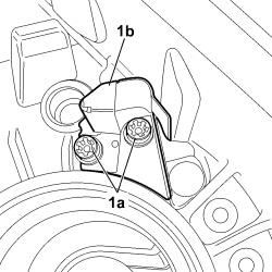
|
1. Undo the fixing screws (1a) and remove the oil duct (1b).
|
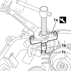
|
1. Use tools (1a) and (1b) to remove the shaft mounting bushes for the gear selection/engagement forks (1c).
|
Usag 468/1 |
Extractor |
Universal extractor |
2.0 JTD 115 HP |
|
Usag 468A/3 |
Extractor |
Removing gear selector and engagement fork shaft support bushes |
2.0 JTD 115 HP |
|
|
|
- DISMANTLE THE MAIN SHAFT BY CARRYING OUT THE OPERATIONS DESCRIBED BELOW.
|
|
Check that the gears do not have notches and that the teeth are not excessively worn. In the event of high mileage it is advisable to replace all the layshaft gears if the main shaft has to be replaced.
|
|
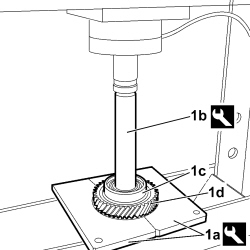
|
1. Position the main shaft in the press, supporting it with tool (1a) and tool (1b), then remove the rear bearing (1c) and the 4th speed gear (1d).
|
2.000.005.000 |
Plates |
Support plates |
2.0 JTD 115 HP |
|
1.860.945.000 |
Fitting tool |
Main shaft bearing |
2.0 JTD 115 HP |
|
|
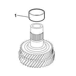
1. Remove the spacer from the main shaft.
|
|
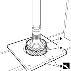
1. Position the main shaft in the press, supporting it with tool (1a). Then remove the 3rd speed gear (1b) and the 5th speed gear (1c).
|
2.000.005.000 |
Plates |
Support plates |
2.0 JTD 115 HP |
|
|
|
- REASSEMBLE THE MAIN SHAFT BY CARRYING OUT THE OPERATIONS DESCRIBED BELOW.
|
|
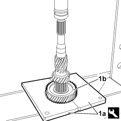
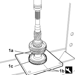
1. Position the main shaft in the press, supporting it with tool (1a), insert gear for 5th speed (1b), respecting the maximum permitted load.
|
2.000.005.000 |
Plates |
Support plates |
2.0 JTD 115 HP |
|
Load to press-fit 5th gear on mainshaft |
10 - 50 kN |
2.0 JTD 115 HP |
|
|
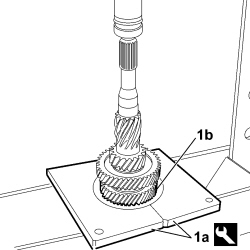
1. Position main shaft in the press, supporting it with tool (1a), insert gear for 3rd speed (1b), respecting the maximum permitted load.
|
2.000.005.000 |
Plates |
Support plates |
2.0 JTD 115 HP |
|
Load to press-fit 3rd gear on mainshaft |
10 - 50 kN |
2.0 JTD 115 HP |
|
|
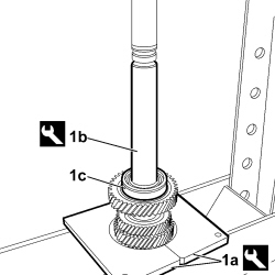
1. Insert spacer (1a), position main shaft in the press, supporting it with tool (1b), insert gear for the 4th speed (1c), respecting the maximum permitted load.
|
2.000.005.000 |
Plates |
Support plates |
2.0 JTD 115 HP |
|
Load to press-fit 4th gear on mainshaft |
8 - 40 kN |
2.0 JTD 115 HP |
|
|
1. Position main shaft in the press, supporting it with tool (1a) and tool (1b), insert the rear bearing (1c), respecting the maximum permitted load.
|
2.000.005.000 |
Plates |
Support plates |
2.0 JTD 115 HP |
|
70465 |
Fitting tool |
Fitting main shaft bearing |
2.0 JTD 115 HP |
|
Load to press-fit rear bearing on main shaft |
11 kN |
2.0 JTD 115 HP |
|
|
|
- DISMANTLE THE LOWER LAYSHAFT BY CARRYING OUT THE OPERATIONS DESCRIBED BELOW.
- Position the lower layshaft in the vice, placing two suitable pieces of protection in between.
|

|
1. Using tool (1a) and plate (1b), remove the rear bearing (1c).
|
Usag 454N/2 |
Extractor |
Layshaft bearing removal |
2.0 JTD 115 HP |
|
1.845.028.000 |
Reaction plate |
Layshaft bearing removal |
2.0 JTD 115 HP |
|
|
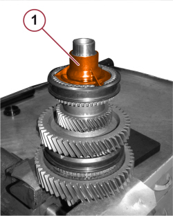
1. Remove the shaft connection sleeve
|
|
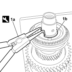
1. Remove the seeger ring (1b) using the pliers (1a).
|
1.870.492.000 |
Calliper |
Removing-refitting snap rings |
2.0 JTD 115 HP |
|
|
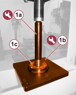
1. Use tool (1a) and plate (1b) to remove the synchroniser assembly (1c) and the 5th speed gear.

|
Keep the synchronizer sleeve centred on the hub while carrying out this operation.
|
|
1.860.945.000 |
Fitting tool |
Main shaft bearing |
2.0 JTD 115 HP |
|
2.000.005.000 |
Plates |
Support plates |
2.0 JTD 115 HP |
|
|
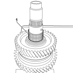
1. Remove the roller bearing.
|
|
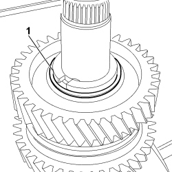
1. Remove the retaining seal for the two half-rings.
|
|
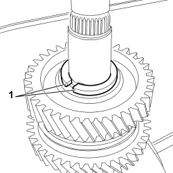
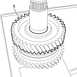
1. Remove the two half-rings.
|
|
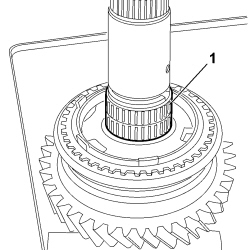
1. Remove the gear for the 2nd speed.
|
|
1. Remove the roller bearing.
|
|
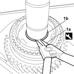
1. Remove the seeger ring (1b) using the pliers (1a).
|
1.870.492.000 |
Calliper |
Removing-refitting snap rings |
2.0 JTD 115 HP |
|
|
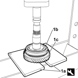
1. Position the lower layshaft in the press, supporting it with tool (1a), remove synchroniser assembly for 1st and 2nd speeds (1b) and gear for 1st speed (1c).
|
|
Keep the synchronizer sleeve centred on the hub while carrying out this operation.
|
|
2.000.005.000 |
Plates |
Support plates |
2.0 JTD 115 HP |
|
|
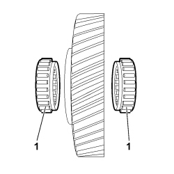
1. Remove the bearings for the 1st speed gear.
|
|
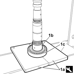
1. Position lower layshaft in the press, supporting it with tool (1a), remove spacer (1b) and front bearing (1c).
|
2.000.005.000 |
Plates |
Support plates |
2.0 JTD 115 HP |
|
|
|
- REASSEMBLE THE LOWER LAYSHAFT BY CARRYING OUT THE OPERATIONS DESCRIBED BELOW.
|
|
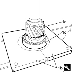
1. Position lower layshaft (1a) in the press, supporting it with tool (1b), insert front bearing (1c), respecting the maximum permitted load.
|
2.000.005.000 |
Plates |
Support plates |
2.0 JTD 115 HP |
|
Load to press-fit front bearing on lower layshaft |
0 - 2 kN |
2.0 JTD 115 HP |
|
|
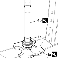
1. Position lower layshaft in the press, supporting it with tool (1a), then insert spacer (1c) using tool (1b).
|
2.000.005.000 |
Plates |
Support plates |
2.0 JTD 115 HP |
|
1.870.658.000 |
Fitting tool |
Fitting layshaft bearing |
2.0 JTD 115 HP |
|
|
|
- Check the condition of the two support bearings for the 1st speed gear and replace them if they are damaged or worn.
|
|
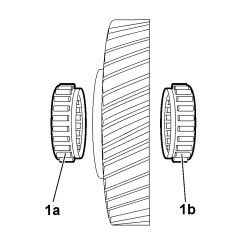
1. Insert two roller bearings (1a) and (1b) inside the 1st speed gear as shown in the diagram.
|
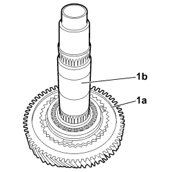
|
1. Insert the 1st speed gear (1a) on the lower layshaft (1b).
|
|
|
- REASSEMBLE THE 1ST AND 2ND SPEED SYNCHRONISER BY CARRYING OUT THE OPERATIONS DESCRIBED BELOW.
|
|
There should not be any signs of wear or ovality on the inner surface of the synchroniser ring.
|
|
|
It is always advisable to replace the synchroniser ring.
|
|
|
Check that the hub and the engagement sliding sleeve are free from any notches and that they slide without too much clearance or sticking. The sleeve inner teeth should not be worn; replace them if they are. Check the condition of the thrust springs and balls and, if necessary, replace the complete insert.
|
|
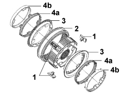
|
1. Place the inserts into their seats on the hub.
2. Insert the sleeve.
3. Fit the synchronizer rings onto the hub.
4. Fit tapered rings (4a) and (4b) onto the synchronizer rings.
|
|
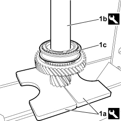
1. Position the lower layshaft in the press, supporting it with tool (1a), then insert synchroniser for 1st and 2nd speeds (1c) using tool (1b) and centring the protrusions on the synchroniser tapered ring with their respective housings on the 1st speed gear. Respect the maximum permitted load during this operation.
|
2.000.005.000 |
Plates |
Support plates |
2.0 JTD 115 HP |
|
1.870.658.000 |
Fitting tool |
Fitting layshaft bearing |
2.0 JTD 115 HP |
|
Load to press-fit 1st and 2nd speed synchronizer |
7 - 31 kN |
2.0 JTD 115 HP |
|
|
Check that the 1st speed gear rotates freely.
|
|
|
|
- Position the lower layshaft in the vice, placing two suitable pieces of protection in between.
- Check the condition of the roller bearing; replace it if damaged or worn.
|
|
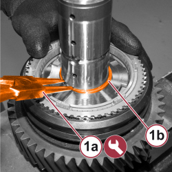
1. Fit the seeger ring (1b) using the pliers (1a).
|
1.870.492.000 |
Calliper |
Removing-refitting snap rings |
2.0 JTD 115 HP |
|
|
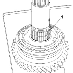
1. Insert the roller bearing.
|
|
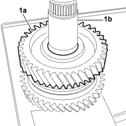
1. Insert the 2nd speed gear (1a) into the lower layshaft (1b).
|
|
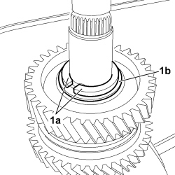
1. Insert the two half-rings (1a) and retaining ring (1b).
|
|
|
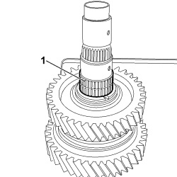
- Check the condition of the roller bearing; replace it if damaged or worn.
|
|
1. Insert the roller bearing.
|
|
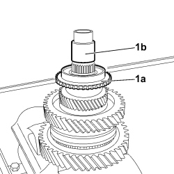
1. Insert the 5th speed gear (1a) into the lower layshaft (1b).
|
|
|
- REASSEMBLE THE 5TH SPEED SYNCHRONISER BY CARRYING OUT THE OPERATIONS DESCRIBED BELOW.
|
|
There should not be any signs of wear or ovality on the inner surface of the synchroniser ring.
|
|
|
It is always advisable to replace the synchroniser ring.
|
|
|
Check that the hub and the engagement sliding sleeve are free from any notches and that they slide without too much clearance or sticking. The sleeve inner teeth should not be worn; replace them if they are. Check the condition of the thrust springs and balls and, if necessary, replace the complete insert.
|
|
|
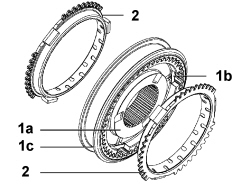
1. Place the inserts (1b) and the sleeve (1c) into their seats on the hub (1a).
2. Fit the synchronizer rings onto the hub.
|
|
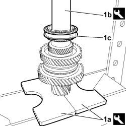
1. Position the main shaft in the press, supporting it with tool (1a), then insert the synchroniser for 5th speed (1c) using tool (1b) and centring the protrusions on the synchroniser ring with their respective housings on the 5th speed gear. Respect the maximum permitted load during this operation.
|
2.000.005.000 |
Plates |
Support plates |
2.0 JTD 115 HP |
|
1.870.658.000 |
Fitting tool |
Fitting layshaft bearing |
2.0 JTD 115 HP |
|
Load to press-fit 5th speed synchronizer |
7 - 30 kN |
2.0 JTD 115 HP |
|
|
Check that the 5th speed gear rotates freely.
|
|
|
|
- Position the lower layshaft in the vice, placing two suitable pieces of protection in between.
|
|
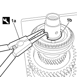
1. Fit the seeger ring (1b) using the pliers (1a).
|
1.870.492.000 |
Calliper |
Removing-refitting snap rings |
2.0 JTD 115 HP |
|
|
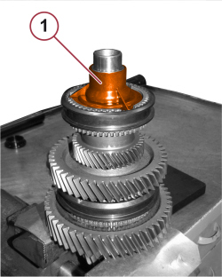
1. Fit the shaft connection sleeve
|
|
|
- DISMANTLE THE UPPER LAYSHAFT BY CARRYING OUT THE OPERATIONS DESCRIBED BELOW.
- Position the upper layshaft in the vice, placing two suitable pieces of protection in between.
|
|
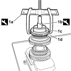
1. Using tool (1a) and plate (1b), remove the rear bearing (1c) and the gear for 4th speed (1d).
|
Usag 454N/2 |
Extractor |
Layshaft bearing removal |
2.0 JTD 115 HP |
|
1.870.812.000 |
Reaction plate |
Layshaft bearing removal |
2.0 JTD 115 HP |
|
|
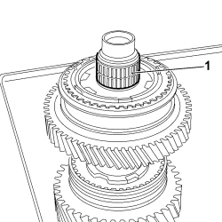
1. Remove the roller bearing.
|
|
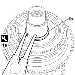
1. Remove the seeger ring (1b) using the pliers (1a).
|
1.870.492.000 |
Calliper |
Removing-refitting snap rings |
2.0 JTD 115 HP |
|
|
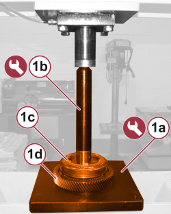
1. Position the upper layshaft in the press and supporting it with the tool (1a), with the tool (1b) remove the synchroniser assembly (1c) for 3rd and 4th speeds and gear (1d) for 3rd speed.
|
2.000.005.000 |
Plates |
Support plates |
2.0 JTD 115 HP |
|
|
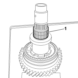
1. Remove the roller bearing.
|
|
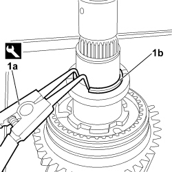
1. Remove the seeger ring (1b) using the pliers (1a).
|
1.870.492.000 |
Calliper |
Removing-refitting snap rings |
2.0 JTD 115 HP |
|
|
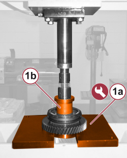
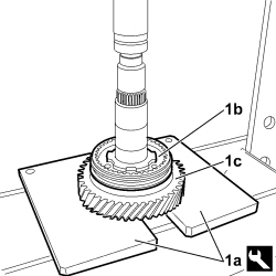
1. Position the upper layshaft in the press, support it with the tool (1a), and remove the spacer (1b).
|
2.000.005.000 |
Plates |
Support plates |
2.0 JTD 115 HP |
|
|
|
2.000.005.000 |
Plates |
Support plates |
2.0 JTD 115 HP |
|
|
Keep the synchronizer sleeve centred on the hub while carrying out this operation.
|
|
|
|
- Position the upper layshaft in the vice, placing two suitable pieces of protection in between.
|
|
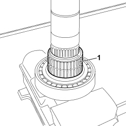
1. Remove the roller bearing.
|
|
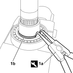
1. Remove the seeger ring (1b) using the pliers (1a).
|
1.870.492.000 |
Calliper |
Removing-refitting snap rings |
2.0 JTD 115 HP |
|
|
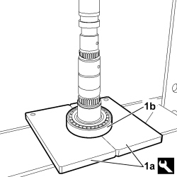
1. Position the upper layshaft in the press, supporting it with tool (1a), and remove front bearing (1b).
|
2.000.005.000 |
Plates |
Support plates |
2.0 JTD 115 HP |
|
|
|
- REASSEMBLE THE UPPER LAYSHAFT BY CARRYING OUT THE OPERATIONS DESCRIBED BELOW.
|
|
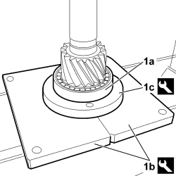
1. Position upper layshaft (1a) in the press, supporting it with tools (1b) and (1c), then insert front bearing (1d), respecting the maximum permitted load.
|
2.000.005.000 |
Plates |
Support plates |
2.0 JTD 115 HP |
|
1.870.658.000 |
Fitting tool |
Fitting layshaft bearing |
2.0 JTD 115 HP |
|
Load to press-fit front bearing on upper layshaft |
14 - 24 kN |
2.0 JTD 115 HP |
|
|
|
- Position the upper layshaft in the vice, placing two suitable pieces of protection in between.
|
|
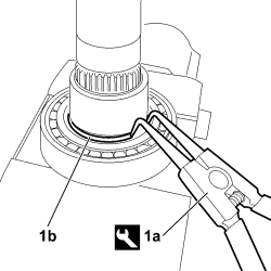
1. Fit the seeger ring (1b) using the pliers (1a).
|
1.870.492.000 |
Calliper |
Removing-refitting snap rings |
2.0 JTD 115 HP |
|
|
|
- Check the condition of the roller bearing; replace it if damaged or worn.
|
|
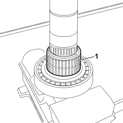
1. Insert the roller bearing.
|
|
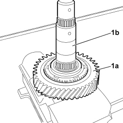
1. Insert the reverse gear (1a) into the upper layshaft (1b).
|
|
|
- REASSEMBLE THE REVERSE SPEED SYNCHRONIZER BY CARRYING OUT THE OPERATIONS DESCRIBED BELOW.
|
|
There should not be any signs of wear or ovality on the inner surface of the synchroniser ring.
|
|
|
It is always advisable to replace the synchroniser ring.
|
|
|
Check that the hub and the engagement sliding sleeve are free from any notches and that they slide without too much clearance or sticking. The sleeve inner teeth should not be worn; replace them if they are. Check the condition of the thrust springs and balls and, if necessary, replace the complete insert.
|
|
|
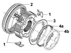
1. Place the inserts into their seats on the hub.
2. Insert the sleeve.
3. Fit the synchroniser ring onto the hub.
4. Fit the tapered rings (4a) and (4b) onto the synchroniser ring.
|
|
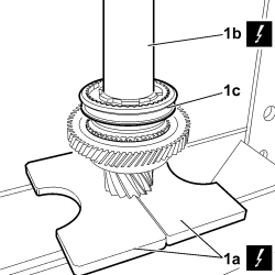
1. Position the upper layshaft in the press, supporting it with tool (1a), then insert synchroniser for reverse speed (1c) using tool (1b) and centring the protrusions on the synchroniser conical ring with their respective housings on the reverse gear. Respect the maximum permitted load during this operation.
|
2.000.005.000 |
Plates |
Support plates |
2.0 JTD 115 HP |
|
1.870.658.000 |
Fitting tool |
Fitting layshaft bearing |
2.0 JTD 115 HP |
|
Load to press-fit reverse synchronizer |
7 - 31 kN |
2.0 JTD 115 HP |
|
|
Check that the reverse gear rotates freely.
|
|
|
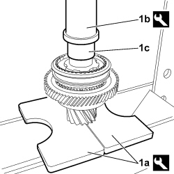
1. Position the upper layshaft in the press, supporting it with tool (1a), then insert spacer (1c) using tool (1b), respecting the maximum permitted load.
|
2.000.005.000 |
Plates |
Support plates |
2.0 JTD 115 HP |
|
1.870.658.000 |
Fitting tool |
Fitting layshaft bearing |
2.0 JTD 115 HP |
|
Load to press-fit spacer on upper layshaft |
2 - 15 kN |
2.0 JTD 115 HP |
|
|
|
- Position the upper layshaft in the vice, placing two suitable pieces of protection in between.
|
|
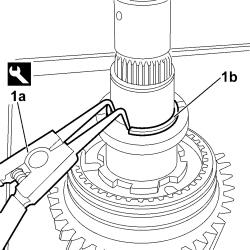
1. Fit the seeger ring (1b) using the pliers (1a).
|
1.870.492.000 |
Calliper |
Removing-refitting snap rings |
2.0 JTD 115 HP |
|
|
|
- Check the condition of the roller bearing; replace it if damaged or worn.
|
|
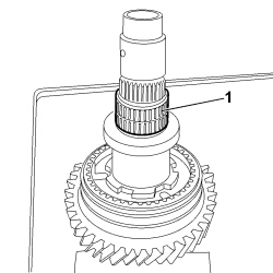
1. Insert the roller bearing.
|
|
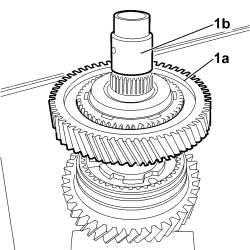
1. Insert the 3rd speed gear (1a) onto the lower layshaft (1b).
|
|
|
- REASSEMBLE THE 3RD AND 4TH SPEED SYNCHRONISER BY CARRYING OUT THE OPERATIONS DESCRIBED BELOW.
|
|
There should not be any signs of wear or ovality on the inner surface of the synchroniser ring.
|
|
|
It is always advisable to replace the synchroniser ring.
|
|
|
Check that the hub and the engagement sliding sleeve are free from any notches and that they slide without too much clearance or sticking. The sleeve inner teeth should not be worn; replace them if they are. Check the condition of the thrust springs and balls and, if necessary, replace the complete insert.
|
|
|
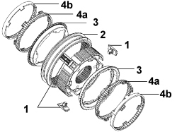
1. Place the inserts into their seats on the hub.
2. Insert the sleeve.
3. Fit the synchronizer rings onto the hub.
4. Fit tapered rings (4a) and (4b) onto the synchronizer rings.
|
|
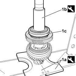
1. Position the upper layshaft in the press, supporting it with tool (1a), then insert synchroniser for 3rd and 4th speeds (1c) using tool (1b) and centring the protrusions on the synchroniser conical ring with their respective housings on the 3rd speed gear. Respect the maximum permitted load during this operation.
|
2.000.005.000 |
Plates |
Support plates |
2.0 JTD 115 HP |
|
1.870.658.000 |
Fitting tool |
Fitting layshaft bearing |
2.0 JTD 115 HP |
|
Load to press-fit 3rd and 4th speed synchronizer |
7 - 30 kN |
2.0 JTD 115 HP |
|
|
Check that the 3rd speed gear rotates freely.
|
|
|
|
- Position the upper layshaft in the vice, placing two suitable pieces of protection in between.
|
|
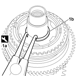
1. Fit the seeger ring (1b) using the pliers (1a).
|
1.870.492.000 |
Calliper |
Removing-refitting snap rings |
2.0 JTD 115 HP |
|
|
|
- Check the condition of the roller bearing; replace it if damaged or worn.
|
|
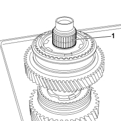
1. Insert the roller bearing.
|
|
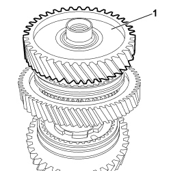
1. Insert the 4th speed gear and centre the housings on the gear, with the protrusions on the synchroniser conical ring.
|
|
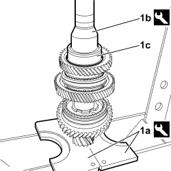
1. Position the lower layshaft in the press, supporting it with tool (1a), then insert rear bearing (1c) using tool (1b).
|
2.000.005.000 |
Plates |
Support plates |
2.0 JTD 115 HP |
|
1.870.658.000 |
Fitting tool |
Fitting layshaft bearing |
2.0 JTD 115 HP |
|
|
|
- Wash the complete gearbox and gearbox gear casing.
|
|
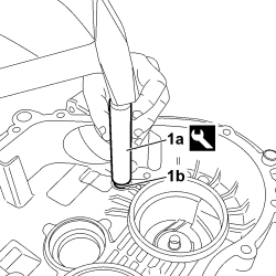
1. Using tool (1a), insert the shaft mounting bushes (1b) for the gear selection/engagement forks into both the gearbox and the gearbox gear casing.
|
1.860.858.000 |
Fitting tool |
Fitting gear selector and engagement fork shaft support bushes |
2.0 JTD 115 HP |
|
|
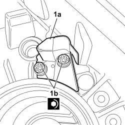
1. Position the oil duct (1a) and tighten the fixing screws (1b) to the prescribed torque.
|
Oil duct |
Screw |
M6 |
0.88 |
2.0 JTD 115 HP |
|
|
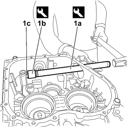
1. Using tools (1a) and (1b), fit the gear selection/engagement shaft bearing (1c).
|
2.000.004.900 |
Drift |
|
2.0 JTD 115 HP |
|
1.874.365.000 |
Fitting tool |
Fitting gear selector bearing |
2.0 JTD 115 HP |
|
|
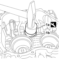
1. Using tool (1a), fit the main shaft bearing (1b) onto the gearbox casing.
|
2.000.019.700 |
Fitting tool |
Bearing fitting tool |
2.0 JTD 115 HP |
|

|
1. Fit the differential casing assembly (1a) with associated bearings (1b) and (1c) onto the gearbox casing.
|
|
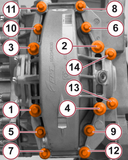
1. Position the differential casing cover and tighten the bolts to the recommended torque, following the order shown.
Tightening torque for screws 1 to 4:
|
Differential casing |
Screw |
M12 |
11.0 |
2.0 JTD 115 HP |
Tightening torque for screws 5 to 14:
|
Differential casing |
Screw |
M10 |
5.0 |
2.0 JTD 115 HP |
|
|
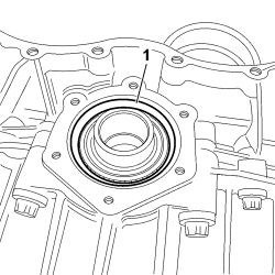
1. Bed in the differential sealing cover side differential bearing outer race.
|
|
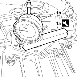
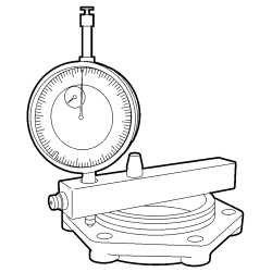
1. Fit tool (1a) complete with dial gauge (1b) on the differential sealing cover support surface, then move the probe into contact with the taper roller bearing outer race.
|
1.895.655.000 |
Mount |
Dial gauge mount |
2.0 JTD 115 HP |
Zero the dial gauge with a preload of 1 mm.
|
|
1. Position tool (1a) complete with dial gauge onto differential sealing cover (1b), as shown in the figure, and measure the difference.
|
1.895.655.000 |
Mount |
Dial gauge mount |
2.0 JTD 115 HP |
|
|
|
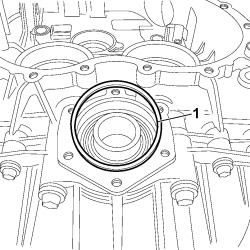
Calculate the thickness of the thrust ring for the differential bearing pre-loading by adding 0.23 mm to the difference measured.
The value of 0.23 mm corresponds to the recommended interference for the bedding in and pre-loading of the differential bearings.
|
|
If one, or the sum of two, registration rings available does not correspond exactly to the value produced in this way, fit one or two rings with a total thickness that is the next largest.
|
|
|
1. Place the thrust ring (of exactly the same size or the next largest size to that calculated for the differential bearing pre-loading) in the housing.
|
|
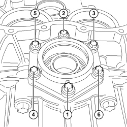
1. Position the differential sealing cover and tighten the fixing screws to the prescribed torque, respecting the order shown.
|
Differential sealing cover |
Screw |
M8 |
2.0 |
2.0 JTD 115 HP |
|
|
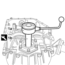
1. Using a dynamometer (1a) and special tool (1b), check that the rotational torque of the differential unit falls within recommended values.
|
2.000.019.600 |
Adapter |
Tool for checking rolling torque at differential |
2.0 JTD 115 HP |
|
Differential mechanism rolling torque assembly |
0 - 3 Nm |
2.0 JTD 115 HP |
|
|
|
- Unscrew the fixing screws and remove the differential sealing cover.
- Remove the differential bearing preload thrust ring from its housing.
- Undo the fixing screws and remove the differential casing cover.
- Remove the differential casing assembly with respective bearings from the gearbox casing.
|
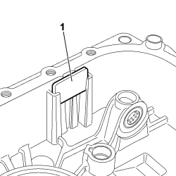
|
1. Position the magnet in its housing on the gearbox casing.
|
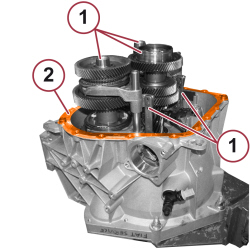
|
1. Position the gearbox shafts, complete with respective gear selection and engagement forks, in their seats on the gearbox casing.
2. Distribute a uniform layer of sealant over the entire contact surface between the gearbox casing and the gearbox gear casing.
|
Gearbox components casing |
Sealant |
Loctite C510 |
|
|
|
|
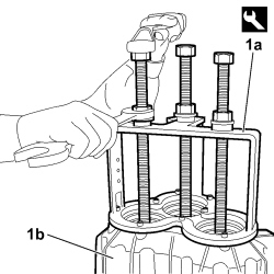
|
1. Fit the gearbox gear casing (1b), using the fitting/extraction tool (1a).
|
2.000.019.400 |
Extractor/fitting tool |
Gearbox casing separator/inserting tool kit |
2.0 JTD 115 HP |
|
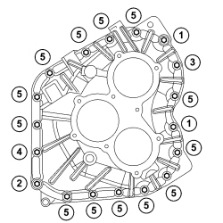
|
1. Tighten the screws fixing the gearbox gear casing to the prescribed torque in two successive stages, following the sequence shown.
In the first stage tighten all the screws to 50% of the rated torque.
In the second stage tighten all the screws to 100% of the rated torque.
|
Gearbox components casing |
Screw |
M8 |
2.2 + 30° |
2.0 JTD 115 HP |
|
|
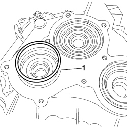
1. Position the shim of the lower layshaft bearing.
|
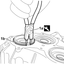
|
1. Using pliers (1a), position the seeger ring (1b) onto the lower layshaft bearing.
|
1.870.492.000 |
Calliper |
Removing-refitting snap rings |
2.0 JTD 115 HP |
|
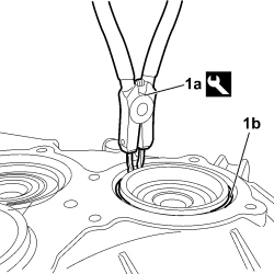
|
1. Using pliers (1a), position the seeger ring (1b) onto the upper layshaft bearing.
|
1.870.492.000 |
Calliper |
Removing-refitting snap rings |
2.0 JTD 115 HP |
|
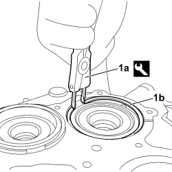
|
1. Using pliers (1a), position the seeger ring (1b) onto the main shaft bearing.
|
1.870.492.000 |
Calliper |
Removing-refitting snap rings |
2.0 JTD 115 HP |
|
|
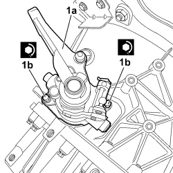
1. Position the gear selection/engagement mechanism (1a) and tighten the screws (1b) to the prescribed torque.
|
Gear selection/engagement mechanism |
Screw |
M8 |
2.0 |
2.0 JTD 115 HP |
|
|
|
- Engage two gears.
|
|
The simultaneous engagement of two gears results in the gearbox shafts locking; this operation is necessary in order to be able to tighten the ring nuts securing the gears to the shafts to torque.
|
|
|
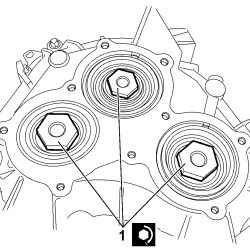
1. Tighten the ring nuts fixing the gears onto the gearbox shafts to the prescribed torque.
|
Ring nut securing gears to main shaft |
Ring nut |
M20x1.5 |
20.0 |
2.0 JTD 115 HP |
|
Ring nut securing gears to layshaft |
Ring nut |
M18x1.5 |
20.0 |
2.0 JTD 115 HP |
|
|
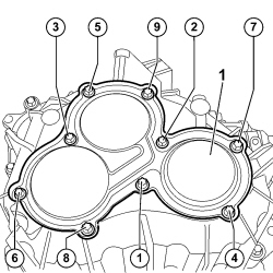
1. Position rear cover (1a) and tighten the fixing screws to the prescribed torque in two successive stages, following the order shown.
In the first stage tighten all the screws to 50% of the rated torque.
In the second stage tighten all the screws to 100% of the rated torque.
|
Gearbox rear cover |
Screw |
M6 |
1.0 |
2.0 JTD 115 HP |
|
|
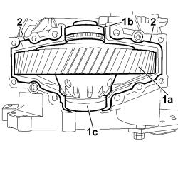
1. Fit the differential casing assembly (1a) with associated bearings (1b) and (1c) onto the gearbox casing.
2. Distribute a uniform layer of sealant over the entire contact surface between the gearbox casing and the differential casing.
|
Gearbox components casing |
Sealant |
Loctite C510 |
|
|
|
|
|
|
- Refit the differential casing cover, the differential bearing preload thrust ring and the differential sealing cover, as shown above.
|
|
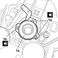
1. Position the clutch release sleeve (1a) and tighten the screws (1b) to the prescribed torque.
|
Clutch release sleeve |
Screw |
M8 |
0.88 |
2.0 JTD 115 HP |
|
|
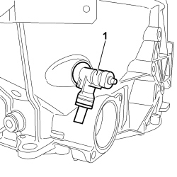
1. Insert the connector between the clutch supply pipe and the clutch release sleeve.
|
|
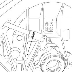
1. Insert the fastening clip for the connector, between the clutch supply pipe and the clutch release sleeve, into the sleeve.
|
|
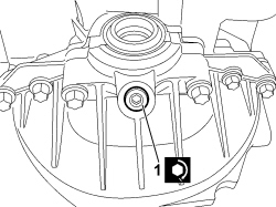
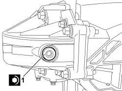
1. Tighten the fluid drain plug on the differential cover to the prescribed torque.
|
Oil level control plug on differential cover |
Plug |
M18x1.5 |
5.0 |
2.0 JTD 115 HP |
|
|
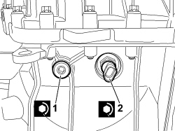
1. Tighten the magnetic plug on the differential cover to the prescribed torque.
|
Oil drain plug on differential cover |
Plug |
M18x1.5 |
5.0 |
2.0 JTD 115 HP |
|
|
1. Tighten the fluid filler cap on the gearbox casing to the prescribed torque.
|
Oil reference plug on gearbox casing |
Plug |
M18x1.5 |
1.0 |
2.0 JTD 115 HP |
2. Tighten the reversing switch to the prescribed torque.
|
Reverse switch |
Plug |
M12x1.5 |
2.0 |
2.0 JTD 115 HP |
|
|
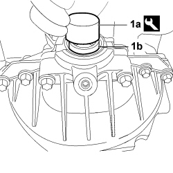
1. Using tool (1a), fit the oil seal (1b) on the differential casing (clutch side).
|
2.000.019.700 |
Fitting tool |
Bearing fitting tool |
2.0 JTD 115 HP |
|
|
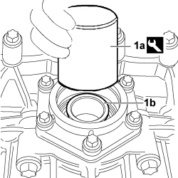
1. Using tool (1a), fit the oil seal (1b) on differential casing (gear casing side).
|
1.871.006.700 |
Fitting tool |
Oil seal fitting |
2.0 JTD 115 HP |
|
|
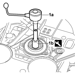
1. Using a dynamometer (1a) and special tool (1b), check that the rotational torque of the main shaft falls within recommended values.
|
2.000.019.500 |
Bush |
Rolling torque checking and reaction bush |
2.0 JTD 115 HP |
|
Main shaft rolling torque |
- Nm |
2.0 JTD 115 HP |
|
|
|
- Support the gearbox using a hydraulic lift.
- Undo the fastenings and remove the gearbox and differential from the support tool.
- Remove the support tool from the overhaul stand.
|
1.871.001.014 |
Support for 1.871.000.000 |
Gearbox fastening for dismantling |
2.0 JTD 115 HP |
- Position the gearbox and differential on a suitable platform.
|