





|
|






|
|
Service News
|
|
Copyright By FCA Italy S.p.A. - Printed 12/02/2014 – Esc.1311
|
|
|
Ducato (250)
Version: all models with RHD
|
|
|
|
|
5570 1 761 RF
|
RADIO AERIAL (RHD)
Interference/noise during reception - Service Solution
|
|
FAULT COMPLAINED OF
Interference in radio signal reception.
TECHNICAL CAUSE
Electromagnetic interference.
OPERATIONS IN NETWORK
Network behaviour standards towards the Customer
-
Once the customer's claimed fault is confirmed, reassure the Customer that it will be solved by fitting an anti-interference filter on aerial wiring.
-
After the operation, show the Customer what has been done and make sure he is satisfied.
Service Solution
Once the claimed fault is confirmed, add an anti-interference filter on aerial wiring, according to the Operating Cycle below.
OPERATION CYCLE
With reference to the Service Manual, proceed as follows.
-
Place the ignition key on STOP, remove the battery cover and disconnect the battery negative terminal, see Op. 5530B10.
Working on the right side of the vehicle:
-
Remove the front side door internal panel (1 - Fig. 1), see Op. 7005E08.
-
Release and remove the internal trim of the front side door frame (2), see Op. 7005E34.
Fig. 1
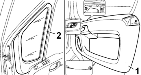
1 - Front side door internal panel
2 - Front side door frame internal trim
-
Remove the under-dashboard cover (1 - Fig. 2), see Op. 7040A60.
Fig. 2
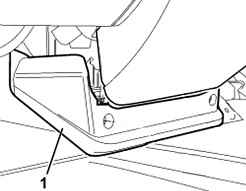
1 - Under-dashboard cover
-
Remove the lower right cover of the dashboard (1 - Fig. 3), with reference to Op. 7040A30
Fig. 3
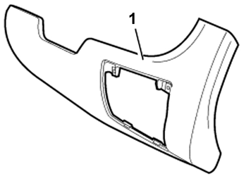
1 - Lower right cover of the dashboard
-
Make a sensor cable (1 - Fig. 4) pass through the cable duct seal, located under the dashboard, on the right post, in the indicated point.
Fig. 4
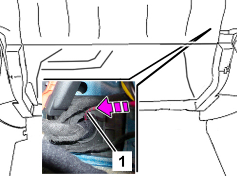
1 - Sensor cable
-
Prise up the cable duct gaiter (2 - Fig. 5) from the post, as shown.
-
Keep the sensor cable (1), make it pass through the gaiter and pull it out from the interior of the door frame, as indicated.
Fig. 5
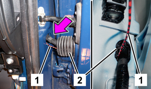
1 - Sensor cable
2 - Cable holder gaiter
-
Take the aerial signal filter kit (1) part no. 1376558080, shown in Fig. 6, from the Spare Parts Dpt., along with the earth lead (G).
Fig. 6
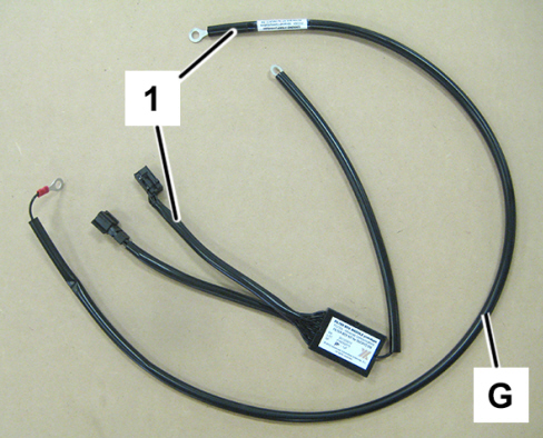
1 - Aerial signal filter kit
G - Earth lead
-
Apply the earth lead (G) from the kit on the terminal of the sensor cable previously applied.
-
Use the sensor cable to make the earth lead pass from the under-dashboard, through the duct seal, then, through the cable-holder gaiter, to the internal part of the door frame.
-
Position the fixing eyelet of the earth lead (G), as shown in Fig. 7, close to the door mirror lower fixing point.
Fig. 7
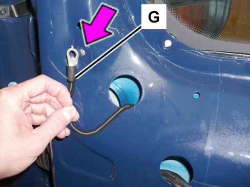
G - Earth lead
-
Disconnect the male connector (1 - Fig. 8) from the door mirror connection shown.
Fig. 8
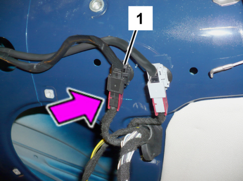
1 - Connector
-
Connect the male connector (1 - Fig. 9), previously disconnected, to the female connector (B) of the aerial signal filter (A).
-
Connect the male connector (C) of the aerial signal filter to the female connector (2) secured to the door frame.
Fig. 9
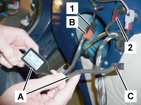
1 - Male connector
2 - Female connector
A - Aerial signal filter
B - Female connector for the filter
C - Male connector for the filter
-
Make the earth lead of the aerial signal filter (A - Fig. 10) pass through the slots on the framework and place the terminal close to the lower fixing screw for the door mirror, as shown.
-
Overlap the earth lead (G) - available in the kit - to the earth lead of the aerial signal filter (A), using the screw (1) fixing the door mirror.
Fig. 10
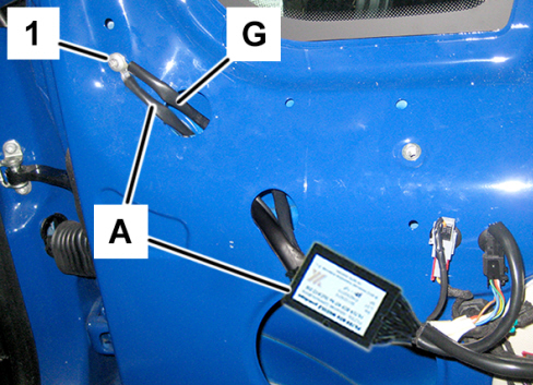
A – Earth lead for the aerial signal filter
G - Earth lead supplied in the kit
1 - Fixing screw for the door mirror
-
Wrap the aerial signal filter (A - Fig. 11) around the wiring, using felt adhesive tape.
-
Make the cable bundle flat against the door structure, as shown.
Fig. 11
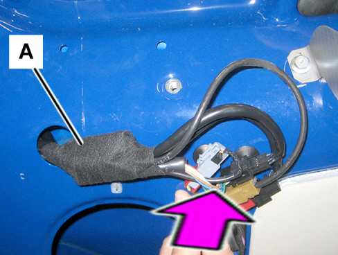
A - Aerial signal filter
-
Connect the earth lead (G - Fig. 12), supplied in the kit, to the earth point located under the dashboard, on the right post.
-
Tighten the fixing nut (1) to the torque of 0.8 daNm.
Fig. 12

G - Earth lead (supplied in the kit)
1 - Fixing nut
-
Refit the internal trim of the front side door frame, see Op. 7005E34.
-
Position the front side door internal panel and arrange the aerial signal filter (A - Fig. 13) to prevent any interference, as shown.
Fig. 13
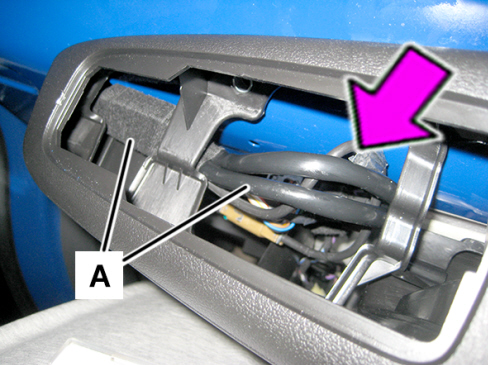
A - Aerial signal filter
-
Refit the panel, see Op. 7005E08.
Then, refit the removed components performing the removal operations on the reverse order.
Connect the negative battery terminal.
AVALABILITY OF PARTS
|
All models in question |
Aerial signal filter kit |
1376558080 |
1 |
|
All models in question |
Nut M6 |
14118711 |
1 (*) |
|
All models in question |
Felt adhesive tape |
71771088 |
1 (**) |
(*) Each pack contains no. 10 nuts
(**) 1.5-m roll; one roll corresponds to 3 repair operations
CLAIM REPORT DATA
|
All models in question |
5570176 |
1 |
RW |
- |
0.90 |
|