1016E10 SINGLE CYLINDER HEAD - DETACHED - OVERHAUL

|
 Removing
(
Refitting Removing
(
Refitting )
)
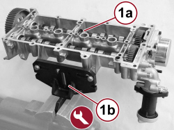
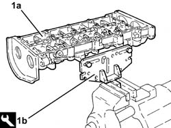
CAMSHAFT HOUSING 1. Position the camshaft housing (1a) in a vice using the tool (1b). |
|
1.860.470.000 |
Mount |
Cylinder head overhaul |
2.0 JTD 115 HP |
|
|
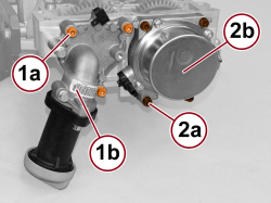
1. Undo the screws (1a) and remove the engine oil filler (1b).
- Remove the gasket.
2. Undo the screws (2a) and remove the vacuum unit (2b).
- Remove the gasket.
|
|
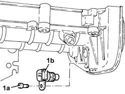
1. Undo the bolt (1a) and remove the cam angle sensor (1b).
|
|
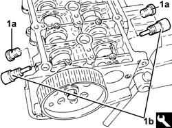
1. Remove the plugs (1a) and fit the camshaft timing tools (1b) on the camshaft housing.

|
Check that the tools are correctly fitted in the housings in the camshafts.
|
|
1.870.896.900 |
Template |
Engine tuning |
2.0 JTD 115 HP |
|
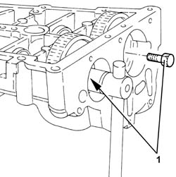
|
1. Undo the bolts securing the camshaft gears.
|
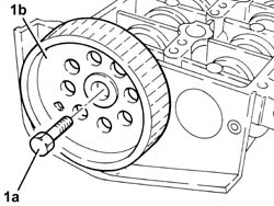
|
1. Undo the bolt (1a) and remove the exhaust side camshaft toothed drive pulley (1b).
|
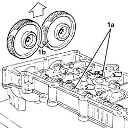
|
- Remove the camshaft timing tools from the camshaft housing.
|
1.870.896.900 |
Template |
Engine tuning |
2.0 JTD 115 HP |
1. Withdraw the camshafts (1a) as far as necessary and remove the camshaft gears (1b).
|
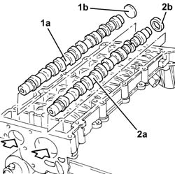
|
1. Using a suitable drift, extract the inlet side camshaft (1a) and the plug (1b).
2. Using a suitable drift, extract the exhaust side camshaft (2a) and the oil seal (2b).
|
|
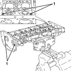
1. Undo and remove the engine oil lubrication duct plugs.
|
|
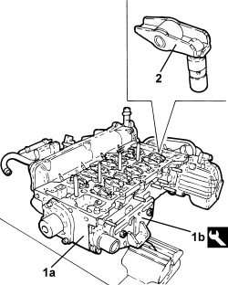
LOWER CYLINDER HEAD 1. Position the cylinder head (1a) in a vice using the tool (1b). |
|
1.860.470.000 |
Mount |
Cylinder head overhaul |
2.0 JTD 115 HP |
2. Remove the tappet assemblies. |
|
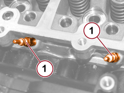
1. Unscrew and remove the heater plugs using the tool.
|
2.000.003.200 |
9 mm heater cap spanner |
Removing/refitting glow heater plugs |
2.0 JTD 115 HP |
|
|
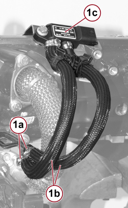
1. Open the bands (1a), disconnect the pressure signal pipes (1b) and remove the differential pressure sensor (1c) complete with bracket and hoses.
|
|
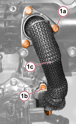
1. Undo the air chamber fixing screws (1a) and the EGR valve fixing screws (1b) and remove the exhaust gas supply pipe to the air chamber (1c) complete with O-ring and gasket.
|
|
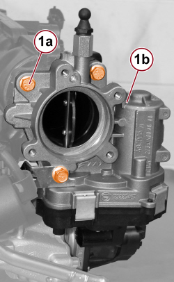
1. Undo the screws (1a) and remove the throttle body (1b).
|
|
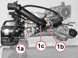
1. Undo the fixing screws (1a) and nuts (1b) and remove the thermostat/EGR valve/EGR heat exchanger assembly (1c).
|
|
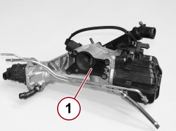
1. Remove the thermostat/EGR valve/EGR heat exchanger assembly gasket.
|
|
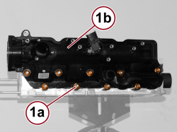
1. Undo the fixing nuts (1a) and remove the air chamber (1b).
|
|
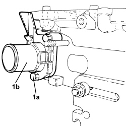
1. Undo the screws (1a) and remove the water pump return connector (1b).
|
|
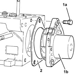
1. Undo the bolts (1a) and remove the water pump (1b).
2. Open the retaining tabs and remove the gasket.
|
|
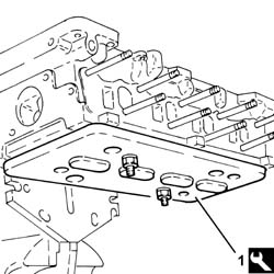
1. Fit a wooden stand on the cylinder head surface to support the valves, and secure it using suitable bolts.
|
1.860.804.000 |
Stand |
Removing/ refitting valves |
2.0 JTD 115 HP |
|
|
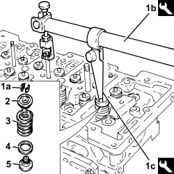
1. Remove half-cones (1a) using tools (1b) and (1c).
|
1.860.644.000 |
Lever |
Removing/ refitting valves |
2.0 JTD 115 HP |
|
2.000.026.800 |
Chamber |
Removing/ refitting valves |
2.0 JTD 115 HP |
2. Remove the valve upper shim.
3. Remove the valve spring.
4. Remove the shim (for exhaust valves only).
5. Remove the valve guide oil seal ring with built-in lower valve shim.
- Carry out the same operations on the other valves.
|
![]() |
|
![]() |
|
|
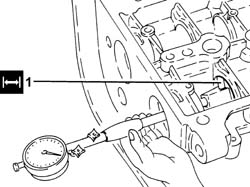
- Check that the valves do not show signs of grooves or meshing.
- Check that the diameter of the valve stems corresponds to the recommended figures; if not, replace the worn valves.
|
Intake valve stem diameter (mm) |
4.982 ÷ 5.000 |
2.0 JTD 115 HP |
|
Exhaust valve stem diameter (mm) |
4.972 ÷ 4.990 |
2.0 JTD 115 HP |
- Check that the length of the valve springs released is within the prescribed values.
|
Valve spring free length (mm) |
44.1 |
2.0 JTD 115 HP |
- Using a torque wrench, check that the valve spring specifications correspond to the prescribed figures; if not, replace the worn components.
|
Length of valve springs under a load of 22.80 - 25.20 daN (mm) |
34.0 |
2.0 JTD 115 HP |
|
Length of valve springs under a load of 43.90 - 48.10 daN (mm) |
25.5 |
2.0 JTD 115 HP |
- Check that the diameter of the camshaft journals corresponds to the recommended figures; if not, replace the worn camshaft.
|
Camshaft first journal diameter (mm) |
43.600 ÷ 43.615 |
2.0 JTD 115 HP |
|
Camshaft second journal diameter (mm) |
43.400 ÷ 43.415 |
2.0 JTD 115 HP |
|
Camshaft third journal diameter (mm) |
43.200 ÷ 43.215 |
2.0 JTD 115 HP |
|
Camshaft fourth journal diameter (mm) |
43.000 ÷ 43.015 |
2.0 JTD 115 HP |
|
Camshaft fifth journal diameter (mm) |
30.000 ÷ 30.015 |
2.0 JTD 115 HP |
- Check that the nominal camshaft cam lift corresponds to the recommended figures; if not, replace the worn camshaft.
|
Nominal intake cam lift (mm) |
8.5 |
2.0 JTD 115 HP |
|
Nominal exhaust cam lift (mm) |
8.0 |
2.0 JTD 115 HP |
1. Check that the diameter of the camshaft supports corresponds to the prescribed figures; if not, replace the upper camshaft housing.
|
Camshaft first support diameter (mm) |
43.646 ÷ 43.671 |
2.0 JTD 115 HP |
|
Camshaft second mounting diameter (mm) |
43.446 ÷ 43.471 |
2.0 JTD 115 HP |
|
Camshaft third support diameter (mm) |
43.246 ÷ 43.271 |
2.0 JTD 115 HP |
|
Camshaft fourth support diameter (mm) |
43.046 ÷ 43.071 |
2.0 JTD 115 HP |
|
Camshaft fifth support diameter (mm) |
30.045 ÷ 30.070 |
2.0 JTD 115 HP |
|
|
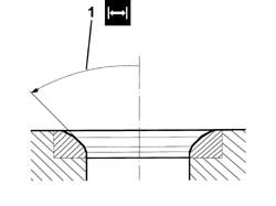
- The outer diameter of the valve housings is as follows.
|
Intake valve seat outer diameter (mm) |
29.600 ÷ 29.611 |
2.0 JTD 115 HP |
|
Exhaust valve seat outer diameter (mm) |
26.100 ÷ 26.111 |
2.0 JTD 115 HP |
1. Grind the valve seats to the prescribed size.
|
Valve seat band angle in contact with valves - inlet |
44° 30’ ÷ 46° 30’ |
2.0 JTD 115 HP |
|
Valve seat band angle in contact with valves - exhaust |
45° ÷ 46° |
2.0 JTD 115 HP |
|
|
- Grind the valve seats using a suitable tool.
LOWER CYLINDER HEAD
- Position the lower cylinder head in the vice using the tool.
|
1.860.470.000 |
Mount |
Cylinder head overhaul |
2.0 JTD 115 HP |
- Fit the valves in the seats, then support them using the wooden stand and secure it using suitable bolts.
|
1.860.804.000 |
Stand |
Removing/ refitting valves |
2.0 JTD 115 HP |
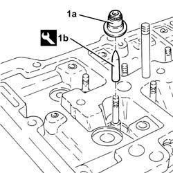
1. Place the valve guide oil seal (1a) in position using the tool (1b).
|
2.000.032.400 |
Extractor/fitting tool |
Extracting/fitting valve guides and fitting oil seal |
2.0 JTD 115 HP |
|
|
|
- Place the shim in position (for exhaust valves only).
- Fit the valve spring in its seat.
- Refit the upper valve shim.
- Place the cotters in their seats with the lever and chamber used for the removal.
- Carry out the same operations on the other valves.
|
|
|
- Remove the wooden stand for supporting the valves from the cylinder head plane.
|
1.860.804.000 |
Stand |
Removing/ refitting valves |
2.0 JTD 115 HP |
- Place a new gasket on the water pump and fold the retaining tabs over.
- Refit the water pump, complete with gasket, in its housing and secure it by tightening the screws to the prescribed torque.
|
Water pump |
Screw (to be replaced) |
M8 |
2.3 ÷ 2.8 |
2.0 JTD 115 HP |
- Place the water pump return connector, complete with new gasket, in position and tighten the screws to the prescribed torque.
|
Water pump inlet pipe |
Screw |
M6 |
0.8 ÷ 1.0 |
2.0 JTD 115 HP |
|
|
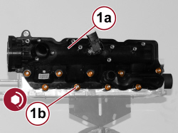
1. Replace the air chamber (1a) in its housing and tighten the nuts (1b) to the prescribed torque.
|
Air chamber |
Nut |
M8 |
2.3 ÷ 2.8 |
2.0 JTD 115 HP |
|
|
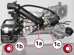
1. Place the thermostat/EGR valve/EGR heat exchanger assembly (1a) complete with new gasket in its housing and tighten the fixing screws (1b) and nuts (1c) to the prescribed torque.
|
EGR valve - heat exchanger - connector pipes assembly |
Screw |
M8 |
2.3 ÷ 2.8 |
2.0 JTD 115 HP |
|
EGR valve - heat exchanger - connector pipes assembly |
Nut |
M8 |
2.3 ÷ 2.8 |
2.0 JTD 115 HP |
|
|
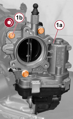
1. Place the throttle body (1a) in its housing and tighten the screws (1b) to the prescribed torque.
|
Throttle body |
Screw |
M8 |
2.3 ÷ 2.8 |
2.0 JTD 115 HP |
|
|
|
- Place the air chamber exhaust gas supply pipe in position complete with new O-ring and tighten the screws.
|
|
Before fitting the pipe, bathe the rubber gasket in soapy water and tighten all the fixing screws before their definitive tightening.
|
- Refit the differential pressure sensor complete with bracket and hoses, connect them and close the bands.
|
|
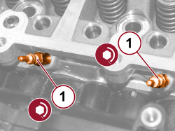
1. Refit the heater plugs in their housing using the tool and tighten them to the prescribed torque.
|
Heater plugs |
- |
M9x1 |
0.7 ÷ 0.9 |
2.0 JTD 115 HP |
|
2.000.003.200 |
9 mm heater cap spanner |
Removing/refitting glow heater plugs |
2.0 JTD 115 HP |
|
|
- Place the hydraulic tappets complete with rocker arms in their housings.
- Remove the lower cylinder head from the support tool.
|
1.860.470.000 |
Mount |
Cylinder head overhaul |
2.0 JTD 115 HP |
CAMSHAFT HOUSING
1. Position the camshaft housing (1a) in a vice using the tool (1b).
|
1.860.470.000 |
Mount |
Cylinder head overhaul |
2.0 JTD 115 HP |
|
|
- Tighten the engine oil lubrication duct plugs.
- Place the camshafts in their housings.
- Refit the camshaft gears in their housings and secure them without tightening the bolts.
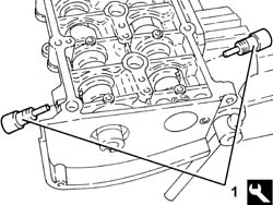
1. Fit the camshaft timing tools.
|
|
Check that the tools are correctly fitted in the housings in the camshafts.
|
|
1.870.896.900 |
Template |
Engine tuning |
2.0 JTD 115 HP |
|
|
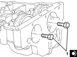
1. Tighten the camshaft gear bolts to the prescribed torque.
|
Camshaft gears |
Screw |
M12 |
2.9 ÷ 3.2 + 48° ÷ 52° |
2.0 JTD 115 HP |
|
|
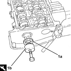
1. Fit the exhaust side camshaft front oil seal (1a) using the tool (1b).
|
1.870.896.800 |
Fitting tool |
Fitting camshaft front oil seal on exhaust side |
2.0 JTD 115 HP |
|
|
- Fit the inlet side camshaft plug.
- Place the exhaust side camshaft toothed drive pulley in its housing and secure it without tightening the bolt.
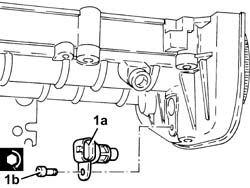
1. Position the cam angle sensor (1a) in its housing and secure it by tightening the screw (1b) to the prescribed torque.
|
Cam angle sensor |
Screw |
M6 |
0.8 ÷ 1.0 |
2.0 JTD 115 HP |
|
|
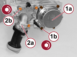
1. Fit the vacuum pump (1a), complete with gasket (1b), back in its housing and secure it by tightening the screws (1c) to the prescribed torque.
|
Vacuum unit to camshaft housing |
Screw |
M6 |
0.7 + 43° ÷ 47° |
2.0 JTD 115 HP |
2. Place the engine oil filler fitting (2a) in its housing complete with gasket and secure it by tightening the screws (2b) to the prescribed torque.
|
Engine oil filler |
Screw |
M6 |
0.8 ÷ 1.0 |
2.0 JTD 115 HP |
|
|
|
- Remove the support tool complete with camshaft housing from the vice and separate them.
|
1.860.470.000 |
Mount |
Cylinder head overhaul |
2.0 JTD 115 HP |
|