CHARACTERISTICSFUNCTIONThe EDC-17C49 Common Rail system is a high pressure electronic injection circuit for fast, direct injection diesel engines. Its main features are:
The main functions of the system are basically as follows:
INJECTION DIAGRAM 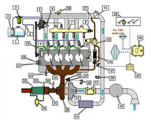
1. Fuel tank 2. Fuel electric pump 3. Fuel filter 4. Fuel return manifold 5. High pressure pump 6. Fuel pressure regulator 7. Single fuel manifold (rail) 8. Fuel pressure sensor 9. Injectors 10. Air cleaner 11. Flow meter 12. Air compressor 13. Intercooler 14. Throttle body 15. EGR valve 16. EGR heat exchanger 17. Exhaust gas supply pipe to intake chamber 18. Air pressure - temperature sensor 19. Engine rpm sensor 20. timing sensor 21. Coolant temperature sensor 22. Engine oil pressure sensor 23. Engine oil level sensor 24. Heater plugs 25. Heater plug control unit 26. Turbine 27. Pneumatic actuator for turbocharger wastegate valve 28. Turbocharger wastegate valve pneumatic actuator control solenoid valve 30. Oxygen sensor 31. Catalytic converter 32. Particle filter (DPF) 33. Exhaust gas temperature sensor 34. Particulate filter differential pressure sensor 35. Accelerator pedal potentiometer 36. Engine management control unit 37. Exhaust gas cooling by-pass for E.G.R. 38. Exhaust gas cooling by-pass control for pneumatic actuator E.G.R. OPERATIONOperating strategiesGeneral informationThe Common Rail system makes it possible to carry out a pre-injection (pilot injection) before T.D.C. This has the advantage of reducing the pressure shift in the combustion chamber, thus reducing the combustion noise typical of direct injection engines. The control unit controls the quantity of fuel injected, regulating the line pressure and injection times. The control unit processes the following information in order to control the quantity of fuel to inject:
Diagram of information entering/leaving the control unit 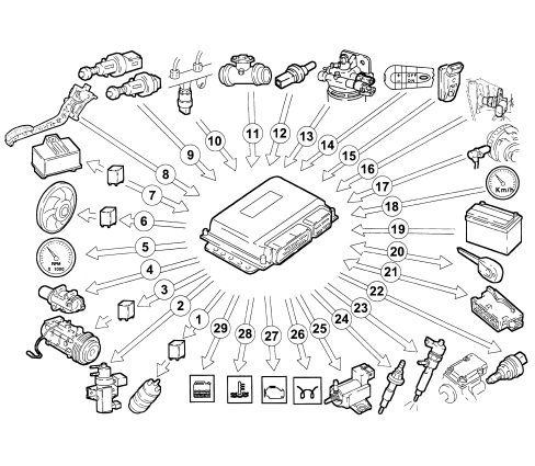
1, Auxiliary fuel pump 2, Turbocharging pressure control solenoid 3, Air conditioner compressor 4, E.G.R. solenoid 5, Rev counter (via CAN) 6, Electric fans 7, Heater plugs control unit 8, Accelerator pedal potentiometer 9, Brake - clutch pedal switch 10, Fuel pressure sensor 11, Air flow meter 12, Coolant temperature sensor 13, Fuel temperature sensor 14, Cruise Control (where fitted) (via CAN) 15, Air pressure and temperature sensor 16, Timing sensor 17, Rpm sensor 18, Speedometer (via CAN) 19, Battery 20, FIAT CODE (via CAN) 21, Diagnostic socket (via CAN) 22, Pressure regulator 23, Injectors 24, Heater plugs 25, Throttle solenoid (on throttle body) 26, Heater plugs warning light (via CAN) 27, Injection warning light (via CAN) 28, Water max temperature warning light (via CAN) 29, Water in fuel warning light (via CAN) Self-diagnosisThe control unit self-diagnosis system checks the signals coming from the sensors and compares them with the permitted limits. FAULT SIGNALS DISPLAYED DURING START UP:
FAULT SIGNALS DISPLAYED DURING OPERATION:
RECOVERY The control unit defines the recovery settings on each specific occasion according to which components are faulty. The recovery parameters are managed by non-faulty components. Fiat code recognitionThe moment the control unit receives the ignition MAR signal, it converses with the body computer (FIAT CODE function) to obtain the go-ahead for start-up. 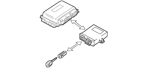
Engine coolant temperature controlWhen the engine coolant temperature is above 105°C, the control unit:
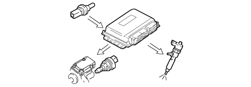
Control of injected fuel quantityThe control unit uses the signals coming from the sensors and the stored values to:
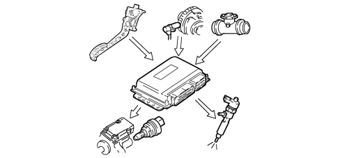
Idling speed controlThe control unit processes the signals coming from the various sensors and regulates the amount of fuel injected:
Within certain thresholds, the speed takes battery voltage into account. 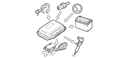
Fuel cut-off during overrunWhen the accelerator pedal is released, the control unit implements the following strategies:
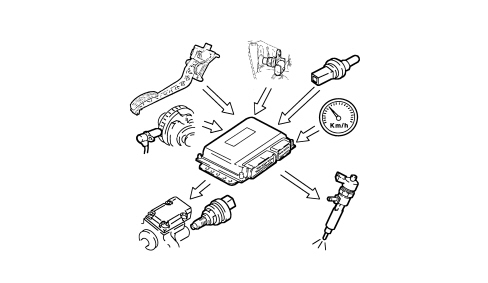
Control of cylinder balancing when idlingAccording to the signals received from the sensors, the control unit monitors torque at idle speed to ensure it is regular:
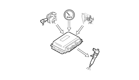
Anti-judder control;The control unit processes the signals received by the various sensors and corrects the quantity of fuel injected in order to improve driveability and reduce jerking whilst driving by means of:
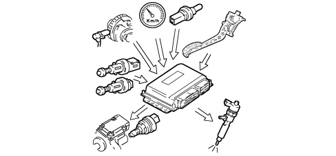
Exhaust fumes control during accelerationIn order to restrict exhaust fumes during fast transitions, the control unit limits the amount of fuel injected according to signals received from the air flow meter and the engine speed, by means of:
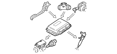
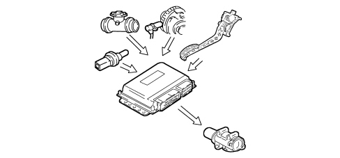
Exhaust gas recirculation (e.g.r.) controlIn accordance with pollution control legislation, on the basis of the engine load and the signal from the accelerator pedal potentiometer, the control unit limits the quantity of intake air, implementing the partial intake of exhaust gases, by:
Maximum torque limit controlThe control unit uses mapped values plotted against rpm to calculate the following:
It compares and corrects these minimum values against other parameters:
and controls the quantity of fuel to be injected (pressure regulator - injectors). 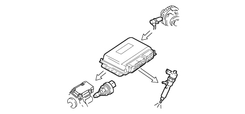
Maximum speed limit controlDepending on the rpm, the control unit implements two intervention strategies:
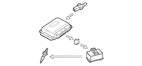
Heater plugs checkThe injection control unit, during the following stages:
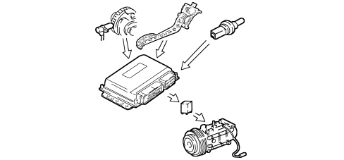
Air conditioning system start-up checkThe control unit operates the air conditioning compressor:
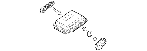
Auxiliary fuel pump controlIrrespective of the rpm, the control unit:
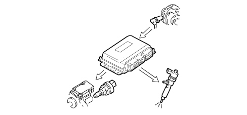
Cylinder position checkDuring each engine revolution, the control unit detects which cylinder is in the combustion phase and controls the injection sequence to the relevant cylinder. 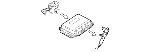
Main and pilot injection advance checkAccording to the signals coming from the various sensors, including the absolute pressure sensor built into the control unit itself, the latter determines the optimum injection point, according to an internal map, based on driving comfort and emission limits. 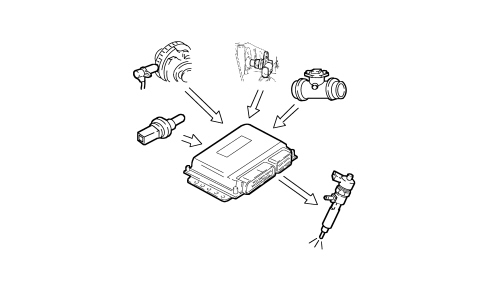
Injection pressure closed loop checkThe control unit controls the regulator to produce optimum line pressure according to engine load, which is determined by processing signals from the various sensors. 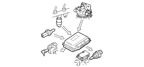
Control of electrical balanceThe control unit modulates the idle speed according to the battery voltage and:
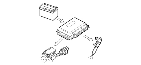
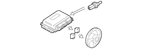
Electric fan controlDepending on the temperature of the engine coolant and the pressure of the air conditioning system coolant, the control unit controls:
Check on throttle closing when switching offIn order to prevent the engine juddering when it is switched off, the control unit immediately closes the inlet throttle. The throttle remains open in all other operating conditions. Cruise control system check (where fitted)Depending on the position of the cruise control lever, the control unit directly manages the quantity of fuel injected in order to control and maintain the vehicle speed which has been memorised. A warning light in the dashboard, activated by the control unit, indicates system operation or deactivation status. The cruise control is temporarily disabled:
The cruise control is not disabled in the event of a request from the accelerator (e.g. to overtake) and automatically restores the vehicle to the set speed as soon as the accelerator is released. The ASR function (antispin) takes precedence over the cruise control for safety reasons. 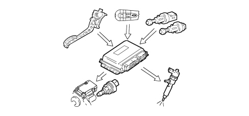
|