SPECIFICATIONS
As far as the exterior lighting equipment is concerned, there are two different vehicle versions, the van/people carrier and the cab version. The differences, illustrated in detail below, involve the lights of the rear side of the vehicle and the side markers. In particular, the rear light clusters on the van/people carrier versions are located vertically on the pillars, whilst on the cab version they are positioned on the rear light cluster crossmember.
On the extra long wheelbase versions, both on the van/people carrier version and on the cab version, the vehicle is equipped with side markers to facilitate identification in poor visibility conditions (the side lights are turned on).
Component location on vehicle (van / people carrier versions)
The vehicle components and their location are illustrated below.
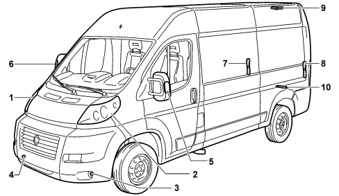
1 - Right front light cluster
2 - Left front light cluster
3 - Left fog light
4 - Right fog light
5 - Left front direction indicator (on mirror)
6 - Right front direction indicator (on mirror)
7 - Right rear light cluster
8 - Left rear light cluster
9 - Third brake light
10 - Number plate lights
Component location on vehicle (cab version)
The vehicle components and their location are illustrated below.
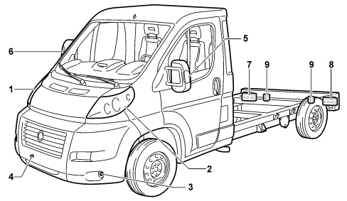
1 - Right front light cluster
2 - Left front light cluster
3 - Left fog light
4 - Right fog light
5 - Left front direction indicator (on mirror)
6 - Right front direction indicator (on mirror)
7 - Right rear light cluster
8 - Left rear light cluster
9 - Number plate lights
Component location on vehicle (van / people carrier extra long version)
The vehicle components and their location are illustrated below.
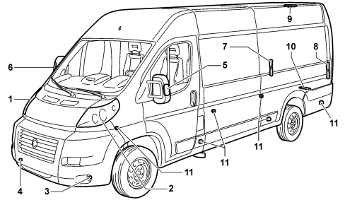
1 - Right front light cluster
2 - Left front light cluster
3 - Left fog light
4 - Right fog light
5 - Left front direction indicator (on mirror)
6 - Right front direction indicator (on mirror)
7 - Right rear light cluster
8 - Left rear light cluster
9 - Third brake light
10 - Number plate lights
11 - Side markers
Component location on vehicle (cab extra long version)
The vehicle components and their location are illustrated below.
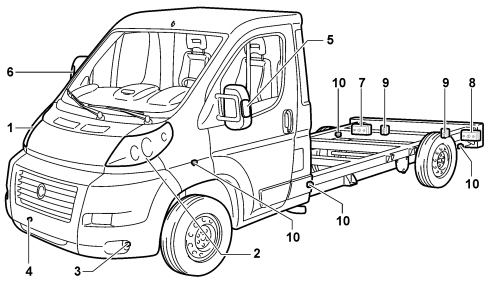
1 - Right front light cluster
2 - Left front light cluster
3 - Left fog light
4 - Right fog light
5 - Left front direction indicator (on mirror)
6 - Right front direction indicator (on mirror)
7 - Right rear light cluster
8 - Left rear light cluster
9 - Number plate lights
10 - Side markers
FRONT LIGHT CLUSTER
The front light clusters are not different for the various versions.
Front view
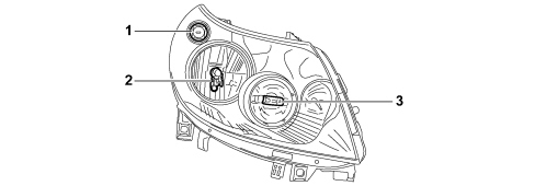
1 - Direction indicator
2 - Side lights / dipped headlamps
3 - Main beam headlamp
Rear view
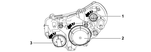
1 - PY21W 21 W type bayonet bulb
2 - All glass W5W 5 W bulb for side lights and H7 55 W halogen bulb for dipped headlamps
3 - H1 55 W halogen bulb
Wiring diagram and connector
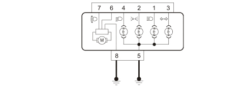

PIN OUT
|
1 |
Main beam headlamps power supply |
|
2 |
Side lights supply |
|
3 |
Direction indicators supply |
|
4 |
Dipped headlamps power supply |
|
5 |
Power earth for lights |
|
6 |
Dipped headlamps on signal for levelling |
|
7 |
Headlight levelling signal |
|
8 |
Headlamp levelling earth |
Electrically controlled headlamp levelling system
The headlamp alignment adjustment device is designed to position the dipped headlamp beam correctly in a vertical direction in order to maintain the correct projection of the light beam whatever the vehicle load level.
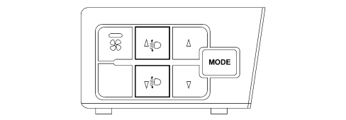
With the dipped headlamps on, adjusting the buttons on the left control panel makes it possible to activate an electric motor inside the headlamps which allows the angle of the front light clusters to be altered in 4 different positions.
For more details,
See E3080 HEADLAMP AGLINMENT CORRECTOR
The instrument panel display, with the dipped headlamps on, shows the position in relation to the adjustment set.
See descriptions 5560 INSTRUMENTS
FOG LIGHTS
The fog lights are located in the lower part of the front bumper.
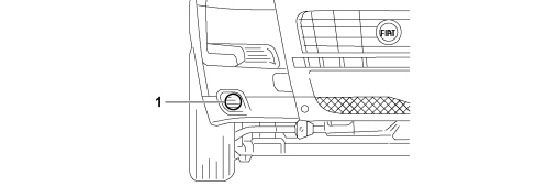
1 - Fog lights
The bulb used for the fog lights function is a halogen H1 55 W bulb.
To replace it, proceed as follows:
-
turn the steering wheel completely to the left;
-
open the flap on the front wheel arch, undoing the self-tapping screw;
-
remove the bayonet cap;
-
disconnect the connector;
-
release the bulb holder clip;
-
extract the bulb and replace it;
-
refit the new bulb, ensuring that the profile of the metal part is aligned with the splining on the curve of the headlight, then reattach the bulb clip and reconnect the electrical connector;
-
refit the bayonet cap.
DIRECTION INDICATORS SIDE REPEATER
The side repeaters for the direction indicators are located on the outer edge of the rear view mirrors.
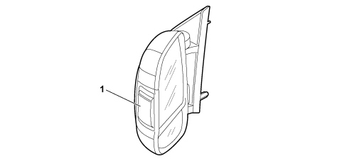
1 - Indicator (all glass WY5W bulb - 5 W or W16WF - 16 W for Extra-long versions)
To change a bulb, move the mirror manually to access the two fixing screws.
Using a Philips screwdriver, undo the screws and extract the bulb holder releasing it from the teeth.
Then undo and replace the bulb, unscrewing it in an anti-clockwise direction.
REAR LIGHT CLUSTER (VAN / PEOPLE CARRIER VERSION)
The rear light clusters are illustrated in the figure.
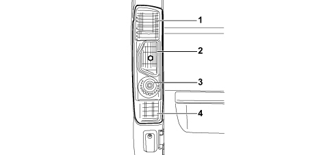
1 - brake/side lights
2 - direction indicators
3 - reversing lights
4 - rear fog lamps
The rear part of the group is shown in the figure:
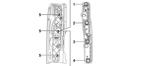
1 - brake/side lights
2 - direction indicators
3 - reversing lights
4 - rear fog lamps
5 - fixing screws
Bulbs present:
-
Brake / side lights: P21/5W 5 W bayonet bulb
-
Direction indicator: PY21W 21 W bayonet bulb
-
Reversing light: P21W 21 W bulb
-
Rear fog light: P21W 21 W bulb
Wiring diagrams and connectors
Connector view (valid for both the left and right lights)
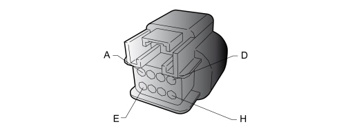
LEFT REAR LIGHT
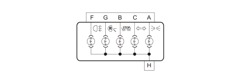
PIN OUT
|
A |
Parking lamp |
|
B |
Brake light |
|
C |
Turn signal indicator |
|
F |
Rear fog light |
|
G |
Reverse light |
|
H |
Earth |
RIGHT REAR LIGHT CLUSTER
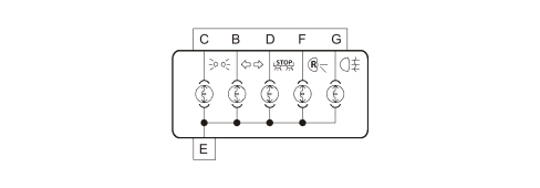
PIN OUT
|
B |
Turn signal indicator |
|
C |
Parking lamp |
|
D |
Brake light |
|
E |
Earth |
|
F |
Reverse light |
|
G |
Rear fog light |
Additional third brake light
The additional brake light function is produced through a multibulb light located in the centre section above the swing doors.
The casing contains the bulb holder which is in one piece and secured to the casing.
The inner tracks supply 4 bayonet type bulbs (P21W - 21 W).
The light has two housings for the fastening. The red coloured metacrylate lens cover is press-fitted on the light casing and its shape and contours are such that when the light is switched off it produces a masking effect if looked at from the outside of the vehicle.
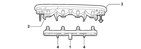
1- Connector
2 - Parabola casing
3 - (Red) lens cover
4 - Tabs for extracting the bulb holder
Number plate light
The number plate light function is achieved by means of two press-fitted light clusters using a metal clip and a reference fastened to the panel.
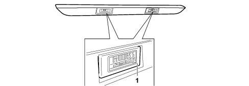
Each lamp is equipped with an all glass bulb C5W- 5 W. To replace, press the side of the lens cover at point 1, removing it from its housing. Then replace the bulb releasing it from the side contacts making sure that the new bulb is correctly secured between the contacts and press-fit the lens cover back in place.
REAR LIGHT CLUSTER (CAB VERSION)
The rear light clusters on the cab version are located on the rear light cluster crossmember, as illustrated in the figure.
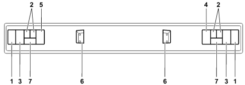
1 - Direction indicators
2 - Side lights
3 - Brake lights
4 - Reversing light
5 - Rear fog lamp
6 - Number plate lights
7 - Transparent reflector
Lorry version rear light clusters
Rear view
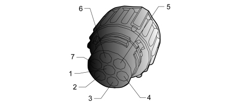
1 - Pin for earth connection
2 - Pin for reversing light connection (in right light cluster only)
3 - Pin for brake lights connection
4 - Pin for direction indicators connection
5 - Pin for rear fog lamp connection (in left light cluster only)
6 - Pin for side lights connection
Cross section view
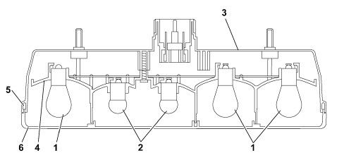
1 - 3 12 V/21 W bulbs for direction indicator, reversing light/rear fog lamp, brake light
2 - 2 12 V/5 W bulbs for side lights
3 - Black polypropylene casing
4 - Polypropylene curve
5 - Sealing gasket
6 - Methacrylate transparent lens cover for reversing light (right light cluster), in red methacrylate for the rear fog lamp (left light)
Wiring diagrams
LEFT REAR LIGHT

PIN OUT
|
1 |
Earth |
|
2 |
Rear fog light |
|
3 |
Brake light |
|
4 |
Turn signal indicator |
|
6 |
Parking lamp |
RIGHT REAR LIGHT CLUSTER

PIN OUT
|
1 |
Earth |
|
3 |
Brake light |
|
4 |
Turn signal indicator |
|
5 |
Reverse light |
|
6 |
Parking lamp |
OPERATION
The operation of the following lights is managed by the Body Computer:
The third brake light is managed directly by the switch on the brake pedal.
The reversing light, on the other hand, is managed directly by the reversing light switch.
Side lights
The side lights are turned on with the key to MAR-ON by the special ring nut on the steering column stalk lights lever. The "parking lights" or "Follow Me Home" functions are also activated (with the key in the OFF position).
Number plate lights
The 2 number plate light bulbs are switched on when there is a request to switch on the side lights or "Parking lights".
Side markers (Extra-long wheelbase versions)
On versions with an extra long wheelbase, the vehicle is equipped with various side markers (6 or 4, depending on whether it is a van/people carrier version or a cab version) which make the vehicle easier to see in poor visibility conditions.
These lights are automatically activated when the side lights are turned on.
Dipped beam headlights
The dipped headlamps are turned on with the key to MAR-ON by the special ring nut on the steering column stalk lights lever. They are also turned on, with the ignition OFF, when the "Follow Me Home" function is activated.
Main beam headlights
The main beam headlamps can be activated (in fixed mode), with the dipped headlamps on, using the special control on the steering column stalk lights lever. The dipped headlamps are disabled when they are activated.
The subsequent deactivation of the main beam headlamps control, with the dipped headlamps control activated, switches the dipped headlamps back on.
Direction indicators/hazard warning lights
Following the direction indicator commands using the left steering column switch unit lever, with the Key ON, the Body Computer operates the direction indicator bulbs individually on the side of the vehicle selected (left front, side and rear or right front, side and rear).
When the lever is returned to the rest position, the lights and the other direction indicators go out.
If the direction indicators are on, they go out at the Key OFF.
At the same time as the operation of the bulbs, there is an acoustic signal from the buzzer inside the instrument panel.
See descriptions 5560
At the operation of the hazard warning lights, at both the Key ON or Key OFF, the Body Computer operates all 6 direction indicator bulbs (front, side and rear, left and right) with the activation of the LED in the hazard warning lights button and the acoustic signal inside the passenger compartment as well.
Brake lights
When the brake pedal is pressed the two brake light bulbs in the rear light clusters light up plus the third brake light present on van / people carrier versions.
Fog lights
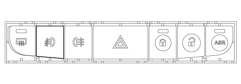
The fog lights are turned on by pressing the fog lights button in the centre switch panel and they only come on if the side lights are already on.
Rear fog lights
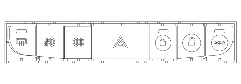
The rear fog lamp is turned on by pressing the button in the centre switch panel. It only comes on if the dipped headlamps or the fog lights are already on.
Parking lights
This function makes it possible to switch on the side lights and the number plate lights with the ignition OFF, to signal the presence of the vehicle whilst it is parked.
Follow me home function
This allows the space surrounding the vehicle to be lit up for a certain period of time.
It is activated by a command with the ignition key in the OFF position or extracted by pulling the lever towards the steering wheel and operating the lever within 2 minutes of the engine switching off.
Each time the lever is operated the length of time the lights stay on is prolonged by 30 seconds up to a maximum of 210 seconds; after this period the lights are switched off automatically.
Each movement of the stalk only increases the amount of time the lights stay on.
To deactivate the function, keep the lever pulled towards the steering wheel for longer than 2 seconds.
|