
|
 Removing
(
Refitting Removing
(
Refitting )
)
- Turn the ignition key to the OFF position. - Remove the battery cover. Op. 5530B54 - Disconnect the negative battery terminal.
- Remove the spare wheel. - Remove both pneumatic springs. Op. 4430C60 PNEUMATIC SPRING (ONE) LEFT OR RIGHT FOR SELF-LEVELLING SUSPENSION SYSTEM - R.R. |
|
- Remove the compressed air reservoir. Op. 4430C10 COMPRESSED AIR RESERVOIR FOR SELF-LEVELLING SUSPENSION SYSTEM - R.R. |
|
- Remove the control unit / compressor module guard. Op. 4430B13 SELF-LEVELLING SUSPENSION SYSTEM COMPRESSOR/CONTROL UNIT MODULE GUARD - R.R. |
|
- Remove the control unit/compressor module. Op. 4430B12 SELF-LEVELLING SUSPENSION SYSTEM COMPRESSOR/CONTROL UNIT MODULE |
|
- Remove the air pipe between the control unit/compressor module and the right pneumatic spring. Op. 4430C71 AIR PIPE FROM CONTROL UNIT MODULE/RIGHT PNEUMATIC SPRING COMPRESSOR - R.R. |
|
- Remove the air pipe between the control unit/compressor module and the left pneumatic spring. Op. 4430C73 AIR PIPE FROM CONTROL UNIT MODULE/LEFT PNEUMATIC SPRING COMPRESSOR - R.R. |
|
- Remove the air pipe between the control unit/compressor module and the air reservoir. Op. 4430C75 PIPE FROM AIR RESERVOIR FOR CONTROL UNIT MODULE/COMPRESSOR - R.R. |
|
- Remove the air filter for the self-levelling suspension system. Op. 4430C22 SELF-LEVELLING SUSPENSION SYSTEM AIR FILTER - R.R. |
|
- Remove both position sensors for the pneumatic springs. Op. 4430B32 PNEUMATIC SPRING POSITION SENSOR (ONE), LEFT OR RIGHT - R.R. |
|
- Remove the wiring for the self-levelling suspension system. Op. 4430B14 WIRING FOR SELF-LEVELLING SUSPENSION SYSTEM - R.R. |
|
- Remove the Panhard bar. |
|
|
|
1. Loosen the locknut (1a) and the nut (1b) fixing the handbrake adjustment device. 2. Disconnect the ends (2a) of the handbrake cables (2b) from the adjustment device. |
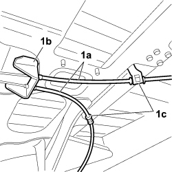 |
1. Release the handbrake cables (1a) from the mounting brackets (1b) and (1c). |
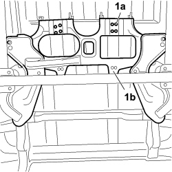 |
1. With the help of a hydraulic lift, undo the bolts (1a) fixing the support (1b) for the self-levelling suspension unit then remove it. |
|
|
Refitting
(
Removing
)
- Check that the support for the self-levelling suspension unit is not damaged or else it must be replaced. |
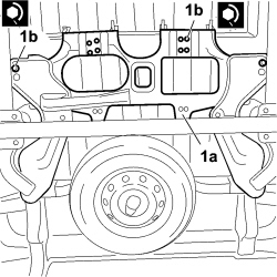 |
1. With the help of a hydraulic lift, position the support (1a) for the self-levelling suspension unit and tighten the fixing bolts (1b) to the recommended torque.
|
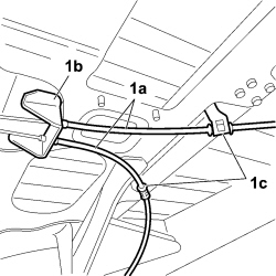 |
1. Secure the handbrake cables (1a) to the mounting brackets (1b) and (1c). |
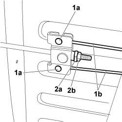 |
1. Connect the ends (1a) of the handbrake cables (1b) to the adjustment device. 2. Screw in the locknut (1a) and the nut (1b) fixing the handbrake adjustment device without tightening them. |
|
|
- Proceed with adjusting the handbrake. |
| - Position the Panhard bar. |
|
- Position the wiring for the self-levelling suspension system. Op. 4430B14 WIRING FOR SELF-LEVELLING SUSPENSION SYSTEM - R.R. |
|
- Position both position sensors for the pneumatic springs. Op. 4430B32 PNEUMATIC SPRING POSITION SENSOR (ONE), LEFT OR RIGHT - R.R. |
|
- Position the air filter for the self-levelling suspension system. Op. 4430C22 SELF-LEVELLING SUSPENSION SYSTEM AIR FILTER - R.R. |
|
- Position the air pipe between the control unit/compressor module and the air reservoir. Op. 4430C75 PIPE FROM AIR RESERVOIR FOR CONTROL UNIT MODULE/COMPRESSOR - R.R. |
|
- Position the air pipe between the control unit/compressor module and the left pneumatic spring. Op. 4430C73 AIR PIPE FROM CONTROL UNIT MODULE/LEFT PNEUMATIC SPRING COMPRESSOR - R.R. |
|
- Position the air pipe between the control unit/compressor module and the right pneumatic spring. Op. 4430C71 AIR PIPE FROM CONTROL UNIT MODULE/RIGHT PNEUMATIC SPRING COMPRESSOR - R.R. |
|
- Position the control unit/compressor module. Op. 4430B12 SELF-LEVELLING SUSPENSION SYSTEM COMPRESSOR/CONTROL UNIT MODULE |
|
- Position the control unit / compressor module guard. Op. 4430B13 SELF-LEVELLING SUSPENSION SYSTEM COMPRESSOR/CONTROL UNIT MODULE GUARD - R.R. |
|
- Position the compressed air reservoir. Op. 4430C10 COMPRESSED AIR RESERVOIR FOR SELF-LEVELLING SUSPENSION SYSTEM - R.R. |
|
- Position both pneumatic springs. Op. 4430C60 PNEUMATIC SPRING (ONE) LEFT OR RIGHT FOR SELF-LEVELLING SUSPENSION SYSTEM - R.R. |
|
- Connect the negative battery terminal.
- Position the battery cover. Op. 5530B54 - Position the spare wheel. |