





|
|






|
|
Service News
|
|
Copyright By FCA Italy S.p.A. - Printed 05/09/2014 – Esc.1568
|
|
|
Ducato (250)
Version: all models
|
|
|
|
|
5050 1 261 RJ
|
WINDSCREEN WIPER MOTOR WIRING
Failed operation - Service Solution
|
|
CLAIMED FAULT
Windscreen wiper failed operation.
TECHNICAL CAUSE
Burnout of the earth wiring of the windscreen wiper motor.
Burnout might be caused by a badly performed emergency start with a booster or additional battery.
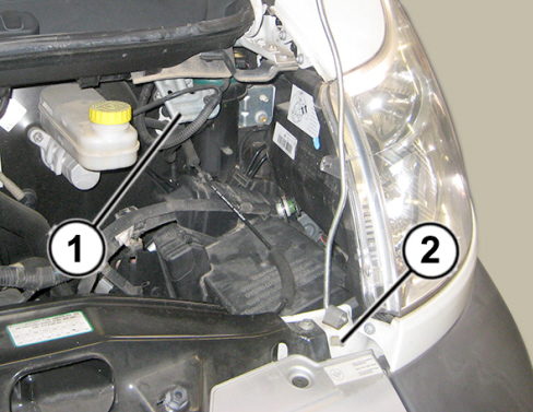
In case of emergency start, the earth connection must be made only and exclusively on terminal 2 of Fig. 1; if the connection is made to other points, such as the windscreen wiper motor bracket (1), the vehicle electrical components might be seriously damaged.
Fig. 1
OPERATIONS AT THE DEALERSHIPS
DEALERSHIP BEHAVIOUR STANDARDS TOWARDS THE CUSTOMER
-
Once the customer's claimed fault is confirmed, reassure the Customer that the fault shall be removed by replacing the connection and the electrical connections of the windscreen wiper motor.
-
After the operation, show the Customer what has been done and make sure he is satisfied.
Service Solution
Once the claimed fault is confirmed, check the electrical connections to the windscreen wiper motor; in case of interrupted connections or short circuits, replace the windscreen wiper motor connection and its cables according to the Operating Cycle below.
OPERATION CYCLE
A - Check
Check the electrical connections of the windscreen wiper motor connector (N015) and in particular the earth connection (refer to the wiring diagram E3020 of the Service Manual).
-
If interrupted connections or short circuits are found, replace the windscreen wiper motor connector and its cables as described in paragraph B below.
-
If the electrical connections of the windscreen wiper motor (N015) are working properly, this Service News cannot be implemented; continue diagnosis to solve the claimed fault (refer to diagnosis J002 of the Service Manual).
B - Replacement of windscreen wiper motor connector and its cables
Turn the ignition key to the STOP position then, with reference to the section "Procedures" of the Service Manual, proceed as follows.
-
Open the bonnet.
-
Remove the battery cover (Op. 5530B54)
-
Disconnect the negative battery terminal.
-
Remove the left front light cluster (Op. 5540B70)
-
Remove the front bumper (Op. 7210E10)
-
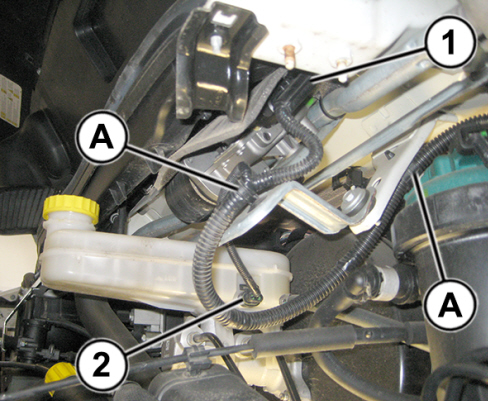
Disconnect the connector of the windscreen wiper motor (1 – Fig. 2).
-
Disconnect the connector of the brake fluid reservoir (2 – Fig. 2).
-
Release the wiring from the fasteners (A – Fig. 2) on the windscreen wiper motor bracket.
Fig. 2
-
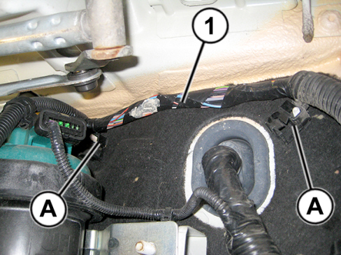
Release the wiring (1 – Fig. 3) from the fasteners on the bulkhead (A).
Fig. 3
-
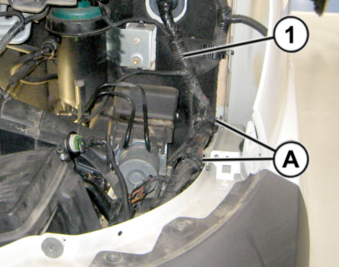
Open the clips for cables (A – Fig. 4) securing the harness (1) to the left side panel.
Fig. 4
-
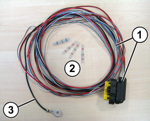
Take from the Spare Parts Dpt. the kit formed by windscreen wiper motor connector with already connected cables (1 – Fig. 5) plus thermal shrinking solder sleeves (2) for the coupling of the supply cable and of the 3 signal cables; the earth cable (3) has an eyelet for the direct connection to the earth point.
Fig. 5
-
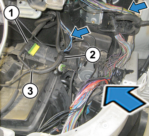
Open the cable clip (2 – Fig. 6) and remove the cable tie (3).
-
Remove the tapings and take out the cables of the corrugated sheath as shown in Fig. 6; find out make sure that one or more cables of the windscreen wiper have been damaged.
-
Replace the connector of the windscreen wiper motor (1 – Fig. 6) laying the new cables in the place of the previous ones, until reaching the side panel area.
-
Identify and take out from the cable wiring the 5 cables to the windscreen wiper motor (supply, earth and 3 signal cables).
-
Excluding the earth cable, cut the other 4 cables (supply and 3 signal cables) with an offset of 4 cm so that the final dimensions of the cable harness can be limited. Splice with the other cables as described in paragraph C - Cable junction - shown at the end of the Operating Cycle.

|
Even though the new cables have the same colours of the previous ones, pay special attention during cable cutting and splicing, complying with the connections. If possible, proceed on one cable at a time.
|
Fig. 6
-
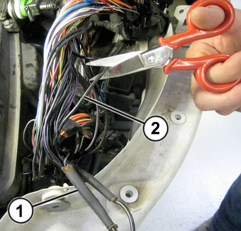
Cut the existing earth cable (2 – Fig. 7) close to the earth coupling (1) and remove it
-
Protect the cut earth cable (2 – Fig. 7) with insulating tape.
Fig. 7
-
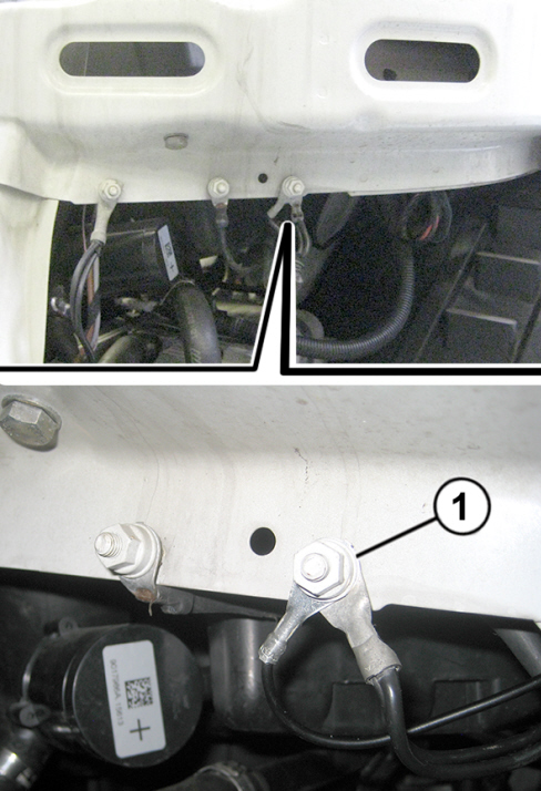
Arrange the new earth cable close to the existing ones, until reaching the earth point on the front left crossmember (1 – Fig. 8) then connect it.
Fig. 8
-
Restore the cable harness fitting the cables inside the corrugated sheath and applying insulating tape if and where required.
-
Make sure that the cable harness is correctly arranged and secured to the retaining clips.
-
Refit all the previously removed components.
C - Cable splicing
Splice the supply cable and the 3 signal cables, proceeding as follows:
-
Using suitable pliers, tool no. 2000027100, strip by about 13 mm the terminals of the cable on the vehicle wiring and of the new cable; fit a thermal shrinking solder sleeve (1 - Fig. 7) and join the strands, as shown in detail (A).

|
The kit (Fig. 6) contains cables and thermal shrinking solder sleeves having a different section: use the sleeves with a smaller diameter (red ring) and those with larger diameter (blue ring) on the corresponding cables with smaller or larger section.
|
-
Twist the terminals as shown in detail (B).
|
|
Make sure not to exceed the cable outside diameter, as shown in detail (B).
|
-
Position the sleeve (1) placing the tin ring in the centre line of the strands, as shown in detail (C).
-
Using a drier fitted with the heat shield tool no. 2000029200 (2) heat the sleeve, as shown in detail (D).
|
|
The drier used in this procedure is available commercially whilst the heat shield (2) is a tool having part number 2000029200.
|

|
While heating the thermal shrinking solver sleeve, as a result of the high temperatures reached, the drier and the heat shield must not, under any circumstances, come into contact with any part of the operator's body and of the car.
|
-
The sleeve (1) must be heated until the adhesive rings stick on the cable, for a perfect sealing and the tin ring melts, welding the coupling, as shown in detail (E).
|
|
Cautiously heat the sleeve (1) to prevent any damage.
Wait until the sleeve cools down before handling the coupling.
|
Fig. 9
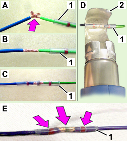
1 - Thermal shrinking solder sleeve
2 - Heat shield - Tool no. 2000029200
PARTS AVALABILITY
|
All models in question |
Windscreen wiper motor connector kit |
1383991080 |
1 |
|
All models in question |
Cable tie with fastener to the body |
51708845 |
1 (*) |
(*) Each pack contains 5 cable ties
CLAIM REPORT DATA
|
All models in question |
5050126 |
1 |
RJ |
- |
0.85 |
|