|
1 |
Check that the connector is fitted correctly in the ignition switch Check that the connectors are fitted correctly in the switch housing |
Connector(s) partially fitted and/or loose, correctly fit the connector(s) in the switch housing and/or replace the loose cable ends if necessary |
|
2 |
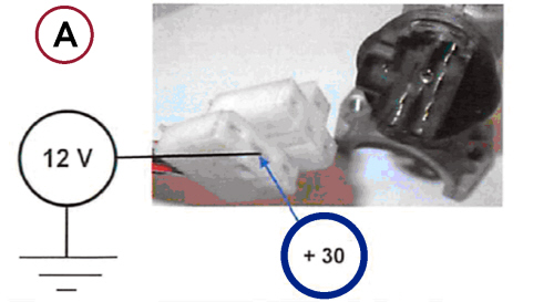
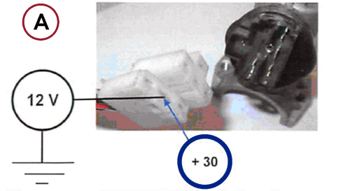
Check for presence of 12 V on the switch Use a multimeter to check that 12 V are present between +30 and the earth (see ref. A) |
No voltage at the connector ends. Determine the cause of the failed supply upstream of the steering lock switch (fuses and/or electrical system interrupted) |
|
3 |
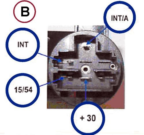
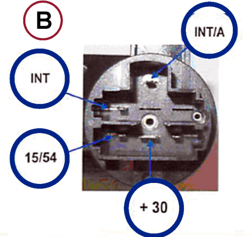
Electrical checks on the switch Disconnect the connections and check (with a multimeter) that the circuits 30-15/54, 30-INT -INT/A in the MAR-ON position on the switch are closed (see ref. B) |
Circuit(s) open, replace the steering lock Op. 5520A14 IGNITION KEY LOCK BARREL - R+R |
|
4 |
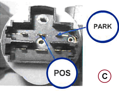
Electrical checks on the switch Disconnect the connections and check that the Park - Pos circuit is closed (see ref. C) (using a multimeter) with the switch in park position |
Circuit open, replace the steering lock Op. 5520A14 IGNITION KEY LOCK BARREL - R+R |
|
1 |
Check that the connector is fitted correctly in the ignition switch Check that the connectors are fitted correctly in the switch housing |
Connector(s) partially fitted and/or loose, correctly fit the connector(s) in the switch housing and/or replace the loose cable ends if necessary |
|
2 |
Check for presence of 12 V on the switch Use a multimeter to check that 12 V are present between +30 and the earth (see ref. A) |
No voltage at the connector ends. Determine the cause of the failed supply upstream of the steering lock switch (fuses and/or electrical system interrupted) |
|
3 |
Electrical checks on the switch Disconnect the connections and check (with a multimeter) that the circuits 30-15/54, 30-INT -INT/A in the MAR-ON position on the switch are closed (see ref. B) |
Circuit(s) open, replace the steering lock Op. 5520A14 |