
|
 Removing
(
Refitting Removing
(
Refitting )
)
- Deactivate the self-levelling suspension control system by simultaneously pressing the two adjustment buttons in the dashboard (for at least 5 secs.) and the LEDs in the buttons should both come on constantly. - Position the vehicle on the lift. - Turn the ignition key to the OFF position. - Remove the battery cover. Op. 5530B54 - Disconnect the negative battery terminal.
- Remove the control unit / compressor module guard. Op. 4430B13 SELF-LEVELLING SUSPENSION SYSTEM COMPRESSOR/CONTROL UNIT MODULE GUARD - R.R. |
|
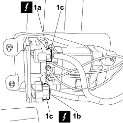 |
1. Disconnect the electrical connectors (1a) and (1b) from the control unit using the anti-release safety slide (1c).
|
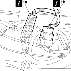 |
1. Disconnect the electrical connectors (1a) and (1b) for the couplings between the wiring for the self-levelling suspension and the left lengthwise wiring.
|
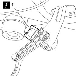 |
1. Disconnect the electrical connectors for the self-levelling suspension position senosrs.
|
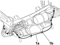 |
1. Release the wiring (1a) from the fastening clips (1b), then remove it. |
|
|
Refitting
(
Removing
)
- Check that the wiring is not damaged, otherwise it must be replaced. - Position the wiring and secure it to the chassis using the retaining clips. - Connect the electrical connectors for the self-levelling suspension position senosrs.
- Connect the electrical connectors for the couplings between the wiring for the self-levelling suspension and the left lengthwise wiring.
- Connect the electrical connectors to the control unit and fit the anti-release safety slide.
- Position the control unit / compressor module guard. Op. 4430B13 SELF-LEVELLING SUSPENSION SYSTEM COMPRESSOR/CONTROL UNIT MODULE GUARD - R.R. |
|
- Connect the negative battery terminal.
- Position the battery cover. Op. 5530B54 - Lower the lift. - Reactivate the self-levelling suspension control system by simultaneously pressing the two adjustment buttons in the dashboard (for at least 5 secs.) and the LEDs in the buttons should both go out. - Check that the system is working properly by carrying out a height alteration cycle. - Remove the vehicle from the lift. |