
|
 Removing
(
Refitting Removing
(
Refitting )
)
- Deactivate the self-levelling suspension control system by simultaneously pressing the two adjustment buttons in the dashboard (for at least 5 secs.) and the LEDs in the buttons should both come on constantly. - Position the vehicle on the lift. - Turn the ignition key to the OFF position. - Remove the battery cover. Op. 5530B54 - Disconnect the negative battery terminal.
- Remove the control unit / compressor module guard. Op. 4430B13 SELF-LEVELLING SUSPENSION SYSTEM COMPRESSOR/CONTROL UNIT MODULE GUARD - R.R. |
|
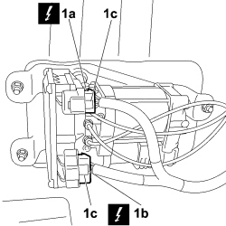 |
1. Disconnect the electrical connectors (1a) and (1b) from the control unit using the anti-release safety slide (1c).
|
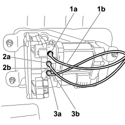 |
1. Slightly undo the connector (1a) for the (black) compressed air pipe (1b) to the accumulation reservoir until the pressure in the circuit is completely discharged then undo the connector completely. 2. Undo the connector (2a) for the red compressed air supply pipe (2b) to the right spring. 3. Undo the connector (3a) for the green compressed air supply pipe (3b) to the left spring. |
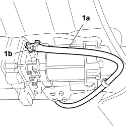 |
1. Disconnect the compressor air inlet pipe (1a) using the rapid connector (1b). |
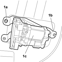 |
1. Undo the nuts (1a) securing the mounting bracket (1b) for the control unit/compressor module and remove the module (1c) complete with bracket. |
 |
1. Remove the tapered inner seal (1b) from the air pipes (1a) disconnected previously from the control unit/compressor module and then release the rapid connector (1c).
|

|
|
Refitting
(
Removing
)
- Check that the control unit/compressor module is not damaged otherwise it must be replaced. |
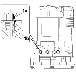 |
1. Tighten new rapid connectors (1a) with tapered inner seals (1b) on the control unit/compressor module.
|

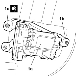 |
1. Place the control unit/compressor module (1a) in position complete with mounting bracket (1b) then secure it tightening the nuts (1c) to the recommended torque.
|
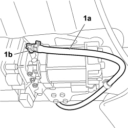 |
1. Connect the compressor air inlet pipe (1a) using the rapid connector (1b). |
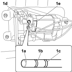 |
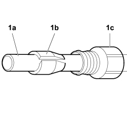
1. There are two reference lines (1b) and (1c) at the ends of the air pipes (1a). Fit the air pipes about 20 mm into the rapid connectors for the control unit/compressor module or as far as necessary to leave only one line (1c) showing following the instructions for the colours given on the label (1e) on the module.
|
 |
1. Connect the electrical connectors (1a) and (1b) to the control unit and fit the anti-release safety slide (1c).
|
|
|
- Position the control unit / compressor module guard. Op. 4430B13 SELF-LEVELLING SUSPENSION SYSTEM COMPRESSOR/CONTROL UNIT MODULE GUARD - R.R. |
|
- Lower the lift until the wheels of the vehicle are touching the ground and keep it at a height where the weight of the vehicle is not weighing on the rear suspension to prevent the air springs from being compressed (completely discharged) and thereby damaged. - Connect the negative battery terminal.
- Position the battery cover. Op. 5530B54 - Start the engine. - Partly inflate the springs using the special control on the Examiner. When refilling using the compressor, two cycles are sufficient with an interval of at least 20 seconds between them. - When refitting the same control unit, reactivate the self-levelling suspension control system by pressing the two adjustment buttons in the dashboard simultaneously (for at least 5 secs.), the LEDs in the buttons will both go out; this procedure does not have to be carried out when replacing the unit because it will have the opposite effect on the new control unit which has nothing stored in the ECU memory. - Leave the engine running for at least 45 minutes without activating the height adjustment buttons; during this peroid the compressor will produce the right pressure in the circuit for correct operation. - Lower the lift completely. - Check that the system is working properly by carrying out a height alteration cycle. - Remove the vehicle from the lift. - If a new control unit / compressor module is used for the refitting, carry out the sensor calibration procedure. Op. 0520G66 SELF-LEVELLING SUSPENSION - CALIBRATION OF SPING POSITION SENSOR USING EXAMINER |