
|
 Removing
(
Refitting Removing
(
Refitting )
)
- Position the vehicle on the lift. Op. 5530B54 - Disconnect the negative battery terminal.
Op. 7055B51 |
|
|
|
Op. 1064B35 PRESSURIZED AIR SUPPLY PIPE TO WASTE GATE VALVE - R.R. |
|
Op. 1064B36 PRESSURIZED AIR SUPPLY PIPE TO WASTE GATE ACTUATOR - R.R. |
|
Op. 1064B44 WASTE GATE VALVE ACTIVATION SOLENOID VALVE - R.R. |
|
Op. 1064B30 WASTEGATE SOLENOID VALVE MOUNTING BRACKET - R.R. |
|
|
|
|
Op. 1048A42 SLEEVE FROM FLOW METER TO TURBO CHARGER AIR INLET PIPE - R + R |
|
|
Op. 1048B20 AIR SUPPLY HOSE FROM HEAT EXCHANGER TO RIGID PIPE - REPLACE |
|
|
|
|
|
Op. 1080C30 PIPE FROM E.G.R. SOLENOID VALVE TO INTAKE MANIFOLD - R.R. |
|
Op. 1080B76 RIGID PRESSURE COLLECTION PIPE UPSTREAM OF THE PARTICULATE FILTER - R.R. |
|
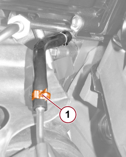 |
1. Undo the band and disconnect the pressure intake hose downstream of the particulate filter. |
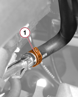 |
1. Open the band and disconnect the coolant supply pipe to the inner heater. |
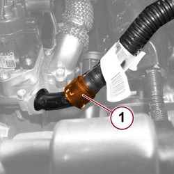 |
1. Disconnect the quick connector for the water/oil exchanger supply pipe |
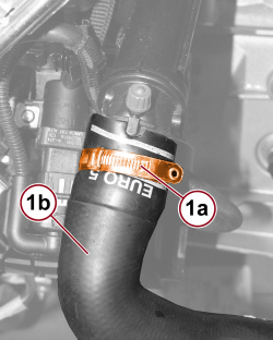 |
1. Open the band (1a) and disconnect the water supply pipe (1b) to the heater. |
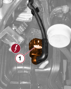 |
1. Disconnect the electrical connection for the water supply actuator control solenoid valve to the EGR heat exchanger.
|
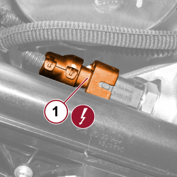 |
1. Detach the electrical connection for the engine coolant temperature sensor.
|
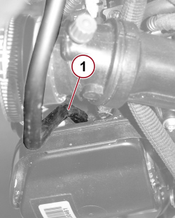 |
1. Disconnect the vacuum pipe for wastegate solenoid valve control. |
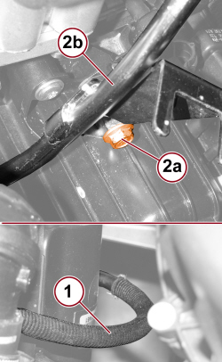 |
1. Disconnect the vacuum pipe from the vacuum reservoir. 2. Undo the screw (2a) fixing the oil dipstick tube (2b) to the vacuum reservoir. |
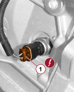 |
1. Disconnect the electrical connection for the reversing light switch and move the wiring to one side.
|
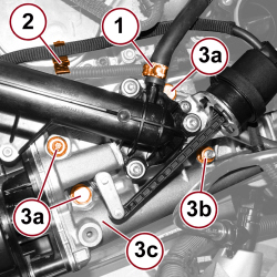 |
1. Open the band and disconnect the degassing pipe from the thermostat. 2. Release the vacuum pipe from the retaining clips. 3. Undo the fixing screws (3a) and nuts (3b) and remove the EGR valve/EGR heat exchanger assembly (3c). |
 |
Refitting
(
Removing
)
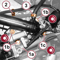
1. Place the EGR valve/EGR heat exchanger assembly (1a) in position and tighten the fixing screws (1b) and the nut (1c) to the prescribed torque. 2. Secure the vacuum pipe to the retaining clips. 3. Connect the degassing pipe to the thermostat and close the band. |
|
|
- Connect the electrical connection for the reversing light switch.
- Tighten the screw fixing the oil dipstick tube to the vacuum reservoir. - Connect the vacuum pipe to the vacuum reservoir. - Connect the vacuum pipe for wastegate solenoid valve control. - Connect the electrical connection for the engine coolant temperature sensor.
- Connect the electrical connection for the water supply actuator control solenoid valve to the EGR heat exchanger.
- Connect the water supply pipe (1b) to the radiator and close the band. - Connect the quick connector for the water/oil exchanger supply pipe - Connect the coolant supply pipe to the inner heater and close the band. - Connect the hose to the pressure intake downstream of the particulate filter and close the band. |
|
|
Op. 1080B76 RIGID PRESSURE COLLECTION PIPE UPSTREAM OF THE PARTICULATE FILTER - R.R. |
|
Op. 1080C30 PIPE FROM E.G.R. SOLENOID VALVE TO INTAKE MANIFOLD - R.R. |
|
|
|
|
|
Op. 1048B20 AIR SUPPLY HOSE FROM HEAT EXCHANGER TO RIGID PIPE - REPLACE |
|
|
Op. 1048A42 SLEEVE FROM FLOW METER TO TURBO CHARGER AIR INLET PIPE - R + R |
|
|
|
|
Op. 1064B30 WASTEGATE SOLENOID VALVE MOUNTING BRACKET - R.R. |
|
Op. 1064B44 WASTE GATE VALVE ACTIVATION SOLENOID VALVE - R.R. |
|
Op. 1064B36 PRESSURIZED AIR SUPPLY PIPE TO WASTE GATE ACTUATOR - R.R. |
|
Op. 1064B35 PRESSURIZED AIR SUPPLY PIPE TO WASTE GATE VALVE - R.R. |
|
|
|
|
Op. 7055B51 - Connect the negative battery terminal.
Op. 5530B54 - Remove the vehicle from the lift. |