
|
 Removing
(
Refitting Removing
(
Refitting )
)
- Open the bonnet. Op. 5530B54 - Disconnect the negative battery terminal.
|
|
|
Op. 1064B35 PRESSURIZED AIR SUPPLY PIPE TO WASTE GATE VALVE - R.R. |
|
Op. 1064B36 PRESSURIZED AIR SUPPLY PIPE TO WASTE GATE ACTUATOR - R.R. |
|
Op. 1064B44 WASTE GATE VALVE ACTIVATION SOLENOID VALVE - R.R. |
|
Op. 1064B30 WASTEGATE SOLENOID VALVE MOUNTING BRACKET - R.R. |
|
|
|
|
Op. 1048A42 SLEEVE FROM FLOW METER TO TURBO CHARGER AIR INLET PIPE - R + R |
|
|
|
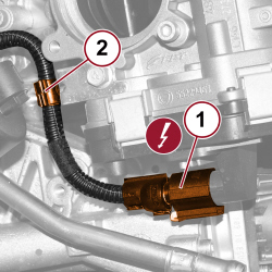 |
1. Detach the electrical connection for the throttle body.
2. Open the retaining clip and release the wiring. |
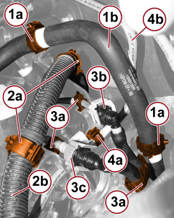 |
1. Open the two retaining clips (1a) and release the coolant supply pipe (1b) to the heater. 2. Open the two retaining clips (2a) and release the wiring (2b). 3. Open the retaining clips (3a) and release the fuel supply (3b) and return (3c) pipes. 4. Open the retaining clip (4a) and release the brake servo vacuum pipe (4b). |
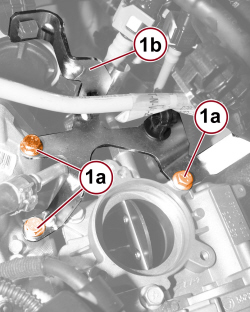 |
1. Undo the screws (1a) and remove the wiring and pipe mounting bracket (1b). |
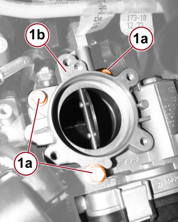 |
1. Undo the fixing screws (1a) and remove the throttle body (1b) |
 |
Refitting
(
Removing
)
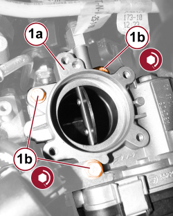
1. Place the throttle body (1a) in position and tighten the fixing screws (1b) to the prescribed torque.
|
|
|
- Place the wiring and pipe mounting bracket in position and tighten the fixing screws. - Engage the brake servo vacuum pipe with the retaining clip. - Secure the fuel supply and return pipes with the retaining clips. - Secure the wiring to the retaining clips. - Engage the heater water supply pipe. - Connect the electrical connection for the throttle body.
|
|
|
|
|
Op. 1048A42 SLEEVE FROM FLOW METER TO TURBO CHARGER AIR INLET PIPE - R + R |
|
|
|
|
Op. 1064B30 WASTEGATE SOLENOID VALVE MOUNTING BRACKET - R.R. |
|
Op. 1064B44 WASTE GATE VALVE ACTIVATION SOLENOID VALVE - R.R. |
|
Op. 1064B36 PRESSURIZED AIR SUPPLY PIPE TO WASTE GATE ACTUATOR - R.R. |
|
Op. 1064B35 PRESSURIZED AIR SUPPLY PIPE TO WASTE GATE VALVE - R.R. |
|
|
|
- Connect the negative battery terminal.
Op. 5530B54 - Close the bonnet. |