Removing ( Refitting )

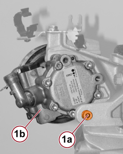
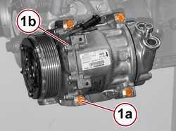
1. Undo the screws (1a) and remove the air conditioner compressor (1b).


1. Undo the rear screw (1a) fixing the power steering pump (1b).


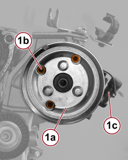
1. Turn the pulley (1a) and undo the screws (1b) through the holes, to remove the power steering pump (1c).


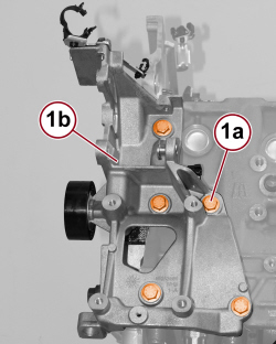
1. Undo the screws (1a) and remove the power steering pump-air conditioner compressor mounting (1b).


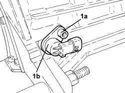
1. Undo the screw (1a) and remove the rpm sensor (1b).


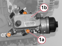
1. Undo the screws (1a) and remove the engine oil filter-heat exchanger mounting (1b).


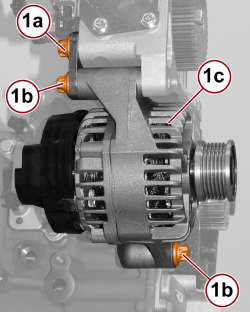
1. Loosen the bolt (1a), undo the bolts (1b) and remove the alternator (1c).


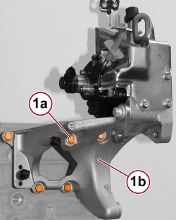
1. Undo the screws (1a) and remove the pressure pump mounting assembly (1b).


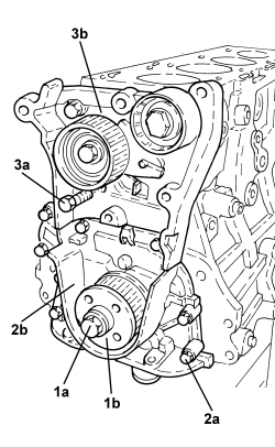
1. Undo the screw (1a) and remove the toothed timing drive pulley (1b), using the flange already fitted on the crankshaft for counter-torque.

2. Undo the screws (2a) and remove the crankshaft oil seal assembly front cover (2b).

3. Undo the screws (3a) and remove the timing drive belt tensioner assembly support (3b).


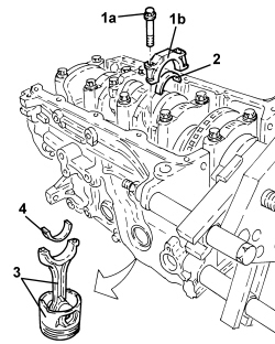
- Rotate the crankshaft with the tool fitted previously until the cylinder concerned is at B.D.C.

1. Undo the screws (1a) and remove the connecting rod cap (1b).

2. Remove the lower connecting rod half-bearing.

3. Remove the connecting rod-piston assembly.

4. Remove the upper connecting rod half-bearing.

- Carry out the same operations to remove the pistons and connecting rods for the remaining cylinders.

- Remove the tool.


Tool


Denomination


Function


Validity


1.860.815.000


Flange


Crankshaft rotation


2.0 JTD 115 HP


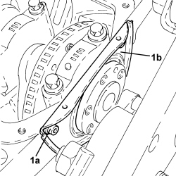
1. Undo the screws (1a), then remove the flywheel side oil seal cover (1b).

- Check that the crankshaft end float corresponds to the prescribed figures using a magnetic base and dial gauge.


Measurement


Value


Validity


Crankshaft end float (mm)


0.049 ÷ 0.211


2.0 JTD 115 HP

- If the value for the crankshaft end float is not within the prescribed limits, when refitting regrind the engine block seat and use suitable oversize thrust half-washers.


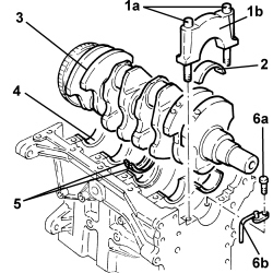
1. Undo the screws (1a) and remove the connecting rod caps (1b).

2. Remove the lower main half-bearings.

3. Remove the crankshaft.

4. Remove the upper main half-bearings.

5. Remove the thrust half-washers.

6. Undo the screws (6a) and remove the jets (6b) from the engine block.

- Remove the engine block from the support tools, then place on a workbench.

    Op. 1028H60 SET OF PISTONS, GUDGEON PINS AND RINGS - REPLACE PISTONS AND CONNECTING RODS AT THE BENCH - INCLUDES ALIGNMENT AND BALANCING

    Op. 1084B18 ENGINE OIL PUMP, REMOVED - CHECK AT THE BENCH

- Drill and remove the water/oil sealing plugs from the engine block to allow for washing the ducts.


Refitting ( Removing )

- Wash the dismantled components.

- Fit the water/oil sealing plugs in the engine block using suitable fitting tools.

- Lubricate all the mechanical coupling components with engine oil.

- Check that the cylinder head support surface does not have cracks or surface grooves.

- Check that the flatness of the cylinder head support surface is within the prescribed limits; if this is not the case, regrind the cylinder head support surface.


Measurement


Value


Validity


Engine cylinder head lower surface flatness (mm)


< 0.1


2.0 JTD 115 HP

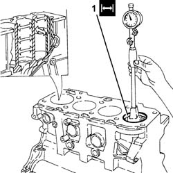
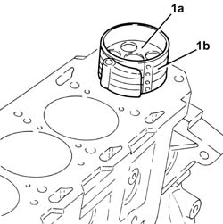
1. Measure the cylinder liner diameter according to the diagram shown in the figure.


Measurement


Value


Validity


Cylinder liner inner diameter - Grade A (mm)


83.000 ÷ 83.010


2.0 JTD 115 HP


Measurement


Value


Validity


Cylinder liner inner diameter - Grade B (mm)


83.010 ÷ 83.020


2.0 JTD 115 HP


Measurement


Value


Validity


Cylinder liner inner diameter - Grade C (mm)


83.020 ÷ 83.030


2.0 JTD 115 HP

- Check that the taper of the cylinder liners is within the prescribed limits.


Measurement


Value


Validity


Cylinder liner taper (mm)


< 0.005


2.0 JTD 115 HP

- Check that the ovality of the cylinder liners is within the prescribed limits.


Measurement


Value


Validity


Cylinder liner ovality (mm)


< 0.05


2.0 JTD 115 HP

- If the cylinder liner measurements are not within the prescribed limits, ream the cylinder liners following the prescribed oversizes.

If reaming, ensure all the liners have the same oversize.


Measurement


Value


Validity


Cylinder liner inner diameter oversize (mm)


0.1


2.0 JTD 115 HP


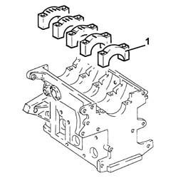
1. Temporarily fit the bearing caps.

The bearing caps have progressively numbered references (from zero to four starting from the front of the engine) which define the fitting position.


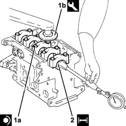
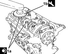
1. Tighten the bearing cap screws (1a) to the prescribed torque using the angular tightening tool (1b).


Component


Fixing


Ø


Value (daNm)


Validity


Bearing caps


Screw


M12


2.4 ÷ 2.6 + 97° ÷ 105°


2.0 JTD 115 HP


Tool


Denomination


Function


Validity


1.895.897.001


Torque wrench


Angular torque tightening


2.0 JTD 115 HP

2. Check that the diameter of the main journal seats is within specified limits.


Measurement


Value


Validity


Main journal seat diameter (mm)


63.705 ÷ 63.718


2.0 JTD 115 HP


- Undo the nuts and remove the bearing caps.

- Check that there are no deposits or blockages in the crankshaft lubrication ducts.

- Check that the diameter of the main journals is within the prescribed limits.


Measurement


Value


Validity


Main journal diameter - Grade A (mm)


59.995 ÷ 60.002


2.0 JTD 115 HP


Measurement


Value


Validity


Main journal diameter - Grade B (mm)


59.988 ÷ 59.995


2.0 JTD 115 HP


Measurement


Value


Validity


Main journal diameter - Grade C (mm)


59.981 ÷ 59.988


2.0 JTD 115 HP

- If the diameter of the main journals is not correct, they should be reground to the prescribed undersize.


Measurement


Value


Validity


Crankpin diameter undersize (mm)


0.127


2.0 JTD 115 HP

Main journal undersizes higher than the value mentioned will adversely affect the structural resistance of the crankshaft (following contact between the tool and rolled connectors). As far as the above is concerned, if the regrinding requires undersizes greater than 0.127 mm, then the crankshaft must be replaced and a new one ordered from the Parts Dept. The half-bearings used for undersizes of more than 0.127 mm should not be ordered from the Parts Dept. (even if the number is still quoted).

- Check that the diameter of the crankpins is within the prescribed limits.


Measurement


Value


Validity


Crankpin diameter - Grade A (mm)


50.800 ÷ 50.807


2.0 JTD 115 HP


Measurement


Value


Validity


Crankpin diameter - Grade B (mm)


50.793 ÷ 50.800


2.0 JTD 115 HP


Measurement


Value


Validity


Crankpin diameter - Grade C (mm)


50.786 ÷ 50.793


2.0 JTD 115 HP

- If the diameter of the crankpins is not correct, they should be reground to the prescribed undersize.


Measurement


Value


Validity


Crankpin diameter undersize (mm)


0.127


2.0 JTD 115 HP

Crankpin undersizes higher than the value given will adversely affect the structural resistance of the crankshaft (following contact between the tool and rolled connectors). As far as the above is concerned, if the regrinding requires undersizes greater than 0.127 mm, then the crankshaft must be replaced and a new one ordered from the Parts Dept. The half-bearings used for undersizes of more than 0.127 mm should not be ordered from the Parts Dept. (even if the number is still quoted).

- Check the main bearings, noting that the half-bearings should not be adapted. If scoring or signs of binding are noted, replace them following the prescribed grade.


Measurement


Value


Validity


Main journal half-bearings - Grade A (Red) (mm)


1.832 ÷ 1.836


2.0 JTD 115 HP


Measurement


Value


Validity


Main journal half-bearings - Grade B (Blue) (mm)


1.835 ÷ 1.839


2.0 JTD 115 HP


Measurement


Value


Validity


Main journal half-bearings - Grade C (Yellow) (mm)


1.838 ÷ 1.842


2.0 JTD 115 HP


Measurement


Value


Validity


Main journal/crankpin half-bearings oversize - Grade A (brown) (mm)


0.127


2.0 JTD 115 HP


Measurement


Value


Validity


Main journal/crankpin half-bearings oversize - Grade B (green) (mm)


0.127


2.0 JTD 115 HP


Measurement


Value


Validity


Main journal/crankpin half-bearings oversize - Grade C (black) (mm)


0.127


2.0 JTD 115 HP


Measurement


Value


Validity


Main journal/crankpin half-bearing oversize (mm)


0.254


2.0 JTD 115 HP

- Fit the half-bearings, making sure they are scrupulously clean.

If the crankshaft has been ground, fit new oversize half-bearings to restore the initial tolerance conditions.

- Fit the crankshaft into its seat on the crankcase.

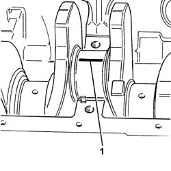
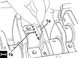
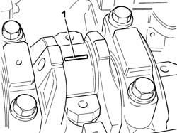
1. Fit the calibrated wire (Plastigage) for measuring the main journal clearance.

Check one journal at a time, without rotating the crankshaft.


1. Fit the main bearing caps complete with half-bearings.

The bearing caps have progressively numbered references (from zero to four starting from the front of the engine) which define the fitting position.


1. Tighten the bearing cap screws (1a) to the prescribed torque using the angular tightening tool (1b).


Component


Fixing


Ø


Value (daNm)


Validity


Bearing caps


Screw


M12


2.4 ÷ 2.6 + 97° ÷ 105°


2.0 JTD 115 HP


Tool


Denomination


Function


Validity


1.895.897.001


Torque wrench


Angular torque tightening


2.0 JTD 115 HP


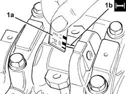
1. Remove the main bearing caps fitted previously and, using a suitably graduated measuring instrument (1a), measure the clearance shown by the calibrated wire (1b).


Measurement


Value


Validity


Clearance between main bearings - crankshaft main journals (mm)


0.031 ÷ 0.051


2.0 JTD 115 HP

If the figure measured is outside of the tolerance, replace the main half-bearings with ones of the correct size and category.


- Measure the clearance for all the bearings, being careful to take the measurements one at a time without moving the crankshaft at all.

- Check that the small end bush bore diameter is within the prescribed limits; if not, replace the worn connecting rod.


Measurement


Value


Validity


Small end bush inner diameter (mm)


30.006 ÷ 30.014


2.0 JTD 115 HP

- Check that the bore of the piston pin housing in the pistons corresponds to the prescribed figures; if not, replace the piston complete with sealing rings, piston pin and bushes.


Measurement


Value


Validity


Gudgeon pin outer diameter (mm)


29.985 ÷ 29.990


2.0 JTD 115 HP

- Check that the outer diameter of the piston pins is within the prescribed limits; if not, replace the worn piston pins.


Measurement


Value


Validity


Gudgeon pin outer diameter (mm)


29.975 ÷ 29.980


2.0 JTD 115 HP

- Fit the sealing rings in the cylinder liner and check that the opening between the ends is within the prescribed values; if this is not the case, replace the retaining rings.


Measurement


Value


Validity


Cylinder compression 1st sealing ring gap (mm)


0.20 ÷ 0.35


2.0 JTD 115 HP


Measurement


Value


Validity


Cylinder compression 2nd sealing ring gap (mm)


0.60 ÷ 0.80


2.0 JTD 115 HP


Measurement


Value


Validity


Engine piston oil scraper ring gap (mm)


0.25 ÷ 0.50


2.0 JTD 115 HP

- Check that the outer diameter of the pistons corresponds to the prescribed figures; if not, replace the piston complete with sealing rings and piston pin.


Measurement


Value


Validity


Piston outer diameter -Grade A (mm)


82.930 ÷ 82.940


2.0 JTD 115 HP


Measurement


Value


Validity


Piston outer diameter - Grade B (mm)


82.940 ÷ 82.950


2.0 JTD 115 HP


Measurement


Value


Validity


Piston outer diameter - Grade C (mm)


82.950 ÷ 82.960


2.0 JTD 115 HP


Measurement


Value


Validity


Piston outer diameter oversize (mm)


0.1


2.0 JTD 115 HP

Measure perpendicular to the gudgeon pin axis, 7 mm from the lower edge of the skirt.

- Check that the seats for piston rings in the piston are within the prescribed limits.


Measurement


Value


Validity


Sealing ring seat in piston - 1st groove (mm)


1.620 ÷ 1.640


2.0 JTD 115 HP


Measurement


Value


Validity


Sealing ring seat in piston - 2nd groove (mm)


1.550 ÷ 1.570


2.0 JTD 115 HP


Measurement


Value


Validity


Sealing ring seat in piston - 3rd groove (mm)


2.020 ÷ 2.040


2.0 JTD 115 HP

- Check that the thickness of the sealing rings is within the prescribed limits.


Measurement


Value


Validity


Cylinder compression 1st sealing ring thickness (mm)


1.470 ÷ 1.495


2.0 JTD 115 HP


Measurement


Value


Validity


Cylinder compression 2nd sealing ring thickness (mm)


1.470 ÷ 1.495


2.0 JTD 115 HP


Measurement


Value


Validity


Cylinder compression 3rd sealing ring thickness (mm)


1.970 ÷ 1.990


2.0 JTD 115 HP

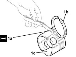
1. Check that the end float (1a) between the first-second ring (1b) and the seats in the piston (1c) corresponds to the prescribed figures.


Measurement


Value


Validity


Cylinder compression 1st sealing ring end float (mm)


0.125 ÷ 0.170


2.0 JTD 115 HP


Measurement


Value


Validity


Cylinder compression 2nd sealing ring end float (mm)


0.055 ÷ 0.100


2.0 JTD 115 HP

- Check that the end float between the oil scraper ring and the housing in the piston corresponds to the prescribed figures.


Measurement


Value


Validity


Engine piston oil scraper ring end float (mm)


0.030 ÷ 0.070


2.0 JTD 115 HP


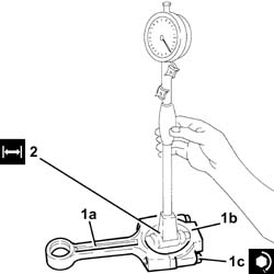
1. Fit the connecting rod caps (1a) on the connection rods themselves (1b), and secure by tightening the screws (1c) to the prescribed torque using tool for angular tightening.


Component


Fixing


Ø


Value (daNm)


Validity


Connecting rod caps


Screw


M9


2.3 ÷ 2.6 + 58° ÷ 62°


2.0 JTD 115 HP


Tool


Denomination


Function


Validity


1.895.897.001


Torque wrench


Angular torque tightening


2.0 JTD 115 HP

2. Check that the big end diameter is within the prescribed limits; if not, replace the connecting rods.


Measurement


Value


Validity


Big end inner diameter (mm)


53.897 ÷ 53.909


2.0 JTD 115 HP


- Undo the nuts and remove the connecting rod caps.

    Op. 1028H60 SET OF PISTONS, GUDGEON PINS AND RINGS - REPLACE PISTONS AND CONNECTING RODS AT THE BENCH - INCLUDES ALIGNMENT AND BALANCING

    Op. 1084B18 ENGINE OIL PUMP, REMOVED - CHECK AT THE BENCH

- Check that there are no signs of seizing on the flywheel ring gear teeth; if this is not the case, replace it.

- Replace the engine block on the overhaul stand using the mounting bracket.


Tool


Denomination


Function


Validity


1.871.000.000


Overhaul stand


Engine overhaul


2.0 JTD 115 HP


Tool


Denomination


Function


Validity


1.871.000.000


Bracket


Positioning engine on overhaul stand


2.0 JTD 115 HP

- Refit the jets in their housings in the engine block and secure them using the screws.

- Refit the thrust half-washers in their seats on the third main bearing.

- The main half-bearings fitted on the crankshaft have been selected for the best specific fitting clearance.

The crankshaft supplied by the Spare Parts Dept. comes without half-bearings and the main journals and crankpins are standard size; the half-bearings to be fitted must therefore be selected by identifying the class of each main journal and crankpin for the new crankshaft.

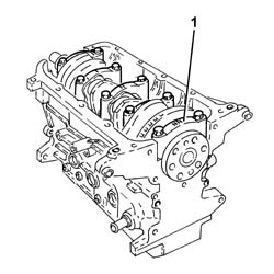
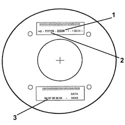
- To select main journal half bearings, measure as follows: the numerical code stamped on the toothed wheel; the paint mark, if present, next to the main journals.

- Below is an example of the identification of main journal grades.

1 - Numerical code of crankpin identification: the left number refers to the first timing side bearing; the final "N" is meaningless for 4 cylinder engines.

2 - Numerical code of main journal identification: the first number on the left refers to the first timing side bearing; the final "N" is meaningless for 4 cylinder engines.

3 - Series of numbers (if present), in groups of two digits, which indicate the dimensions (thousandth part) of the main journals: the first two numbers on the left refer to the first journal, timing side

Only use the codes that relate to the key; all other codes on the toothed wheel should not be used.

To identify the main journal grade, refer to the numerical reference code 2 in the key.

In the example, the numbers 11111N indicate that all five journals are Grade A (red) as indicated below.

A further method for identifying the grade of the bearings is to read reference 3 (if present) in the diagram.

In the case of the example, the number 95 (first on the left) corresponds to the dimensions 59.995 for the first timing side bearing which identifies Grade A (red); the same method should be applied for other groups of two digits for the same reference 3 (97 - 95 - 95 - 94).

MAIN JOURNAL IDENTIFICATION

Main journal grade A (normal), diameter 59.995 - 60.002 mm, RED paint mark, numerical code 1 (95 02)*

Main journal grade B (normal), diameter 59.988 - 59.995 mm, BLUE paint mark, numerical code 2 (88 95)*

Main journal grade C (normal), diameter 59.981 - 59.988 mm, YELLOW paint mark, numerical code 3 (81 88)*

Main journal grade D (0.127 mm undersize), diameter 59.868 - 59.875 mm, BROWN paint mark, numerical code 6 (68 75)*

Main journal grade E (0.127 mm undersize), diameter 59.861 - 59.868 mm, GREEN paint mark, numerical code 7 (61 68)*

Main journal grade F (0.127 mm undersize), diameter 59.854 - 59.861 mm, BLACK paint mark, numerical code 8 (54 61)*

(*) Last two numbers (thousandth part) of the main journal dimensions.

If using a crankshaft where the maximum undersize for the bearings is 0.127 mm through grinding, the grade should be selected by measuring the diameter of the bearing using the above as a reference.

Having defined the grade and the colour of each new or reground crankshaft pin, it is necessary to select the thickness of the pins, which should be the same colour as the corresponding pin; the pair of half-bearings required can be ordered from the Parts Dept. by quoting the order number.

The above is designed to guarantee the optimum operational clearances for all pins.

Lastly, we wish to point out that the clearance between the main journal and the half-bearing, obtained through the selection method indicated above, should generally be within the following values: Minimum: 0.031 mm - Maximum: 0.051 mm; this value can be measured, as a final check, using the calibrated wire (plastic gauge).

- Refit the upper main bearing half-bearings in their seats in the engine block.

- Place the crankshaft in its housing in the crankcase.

- Place the bearing caps complete with lower half-bearings in position.

The bearing caps have progressively numbered references (from zero to four starting from the front of the engine) which define the fitting position.

- Tighten the connecting rod cap screws to the prescribed torque using the angular tightening tool.


Component


Fixing


Ø


Value (daNm)


Validity


Bearing caps


Screw


M12


2.4 ÷ 2.6 + 97° ÷ 105°


2.0 JTD 115 HP


Tool


Denomination


Function


Validity


1.895.897.001


Torque wrench


Angular torque tightening


2.0 JTD 115 HP

- Fit the tool.


Tool


Denomination


Function


Validity


1.860.815.000


Flange


Crankshaft rotation


2.0 JTD 115 HP


- Rotate the crankshaft with the tool fitted previously until the cylinder concerned is at B.D.C.

1. Place the piston and connecting rod assembly (1a) in its housing complete with half-bearing, using a suitable tool (1b).

For the selection of the connecting rod half-bearings, follow the procedure described previously for the main half-bearings according to the grades listed below.


Measurement


Value


Validity


Crankpin half-bearings - Grade A (red) (mm)


1.528 ÷ 1.532


2.0 JTD 115 HP


Measurement


Value


Validity


Crankpin half-bearings - Grade B (blue) (mm)


1.532 ÷ 1.536


2.0 JTD 115 HP


Measurement


Value


Validity


Crankpin half-bearings - Grade C (yellow) (mm)


1.535 ÷ 1.539


2.0 JTD 115 HP


Measurement


Value


Validity


Main journal/crankpin half-bearings oversize - Grade A (brown) (mm)


0.127


2.0 JTD 115 HP


Measurement


Value


Validity


Main journal/crankpin half-bearings oversize - Grade B (green) (mm)


0.127


2.0 JTD 115 HP


Measurement


Value


Validity


Main journal/crankpin half-bearings oversize - Grade C (black) (mm)


0.127


2.0 JTD 115 HP


Measurement


Value


Validity


Main journal/crankpin half-bearing oversize (mm)


0.254


2.0 JTD 115 HP

The piston-connecting rod assemblies should be fitted in the engine block so that the drain on the piston skirt is aligned with the oil jet on the engine block.

- Carry out the same operations to fit the pistons and connecting rods for the remaining cylinders.


1. Test the crankpin clearance by applying the calibrated wire (Plastigage) to measure crankpin installation clearance.

- Place the connecting rod caps complete with half-bearings in their seats.

Fit the connecting rod caps so that the number stamped on each rod faces toward the same side as the number stamped on the big end (inlet side).

- Tighten the screws to the prescribed torque, using the angular tightening tool.


Component


Fixing


Ø


Value (daNm)


Validity


Connecting rod caps


Screw


M9


2.3 ÷ 2.6 + 58° ÷ 62°


2.0 JTD 115 HP


Tool


Denomination


Function


Validity


1.895.897.001


Torque wrench


Angular torque tightening


2.0 JTD 115 HP


- Undo the nuts and remove the connecting rod caps with the half-bearings fitted previously.

1. Use an appropriate graduated measuring tool (1a) to measure the clearance indicated by the calibrated wire (1b).


Measurement


Value


Validity


Clearance between connecting rod bearings - crankpin bearings (mm)


0.030 ÷ 0.056


2.0 JTD 115 HP

- If the value measured is not within the prescribed figures, replace the connecting rod bearings.

- Carry out this test on all the crankpins, one at a time, without ever turning the crankshaft.

- Fit the connecting rod cap complete with half-bearing and secure it without tightening the screws.

Fit the connecting rod caps so that the number stamped on each rod faces toward the same side as the number stamped on the big end (inlet side).

- Tighten the connecting rod cap screws to the prescribed torque using the angular tightening tool.


Component


Fixing


Ø


Value (daNm)


Validity


Connecting rod caps


Screw


M9


2.3 ÷ 2.6 + 58° ÷ 62°


2.0 JTD 115 HP


Tool


Denomination


Function


Validity


1.895.897.001


Torque wrench


Angular torque tightening


2.0 JTD 115 HP

- Remove the tool.


Tool


Denomination


Function


Validity


1.860.815.000


Flange


Crankshaft rotation


2.0 JTD 115 HP

- Place the crankshaft oil seal front cover in its seat complete with gasket and tighten the screws to the prescribed torque.


Component


Fixing


Ø


Value (daNm)


Validity


Crankshaft oil seal front cover


Screw (to be replaced)


M6


0.8 ÷ 1.0


2.0 JTD 115 HP


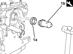
1. Place the seal ring (1a) in its seat on the crankshaft oil seal front cover using the tool (1b).


Tool


Denomination


Function


Validity


2.000.004.100


Fitting tool


Fitting oil pump sealing ring


2.0 JTD 115 HP

- Replace the engine rpm sensor in its housing and secure it by tightening the screw to the prescribed torque.


Component


Fixing


Ø


Value (daNm)


Validity


Rpm sensor


Screw


M6


0.8 ÷ 1.0


2.0 JTD 115 HP

- Place the timing belt tensioner mounting assembly in position and secure it by tightening the screws to the prescribed torque.


Component


Fixing


Ø


Value (daNm)


Validity


Tensioner support to crankcase


Screw


M8


2.3 ÷ 2.8


2.0 JTD 115 HP

- Place the flywheel side cover in its housing and secure it tightening the screws to the prescribed torque.


Component


Fixing


Ø


Value (daNm)


Validity


Flywheel side oil seal cover


Screw (to be replaced)


M6


0.8 ÷ 1.0


2.0 JTD 115 HP

- Apply silicone sealant to the entire perimeter of the engine oil sump.

- Place the oil sump back in its housing.

- Tighten the side screws securing the oil sump to the prescribed torque.


Component


Fixing


Ø


Value (daNm)


Validity


Engine oil sump


Side screws


M8


2.3 ÷ 2.8


2.0 JTD 115 HP

- Tighten the front and rear screws fixing the oil sump to the prescribed torque using the tool.


Component


Fixing


Ø


Value (daNm)


Validity


Engine oil sump


Timing side and gearbox side screws


M6


0.8 ÷ 1.0


2.0 JTD 115 HP

- Fit the tool for the crankshaft rotation, to be used as counter-torque to tighten the toothed drive pulley fixing screw.


Tool


Denomination


Function


Validity


1.860.815.000


Flange


Crankshaft rotation


2.0 JTD 115 HP

- Position the toothed drive pulley in its housing and secure it by tightening the screw to the prescribed torque.


Component


Fixing


Ø


Value (daNm)


Validity


Toothed drive pulley


Left hand screw


M16


32.3 ÷ 35.7


2.0 JTD 115 HP

- Remove the tool for the crankshaft rotation.


Tool


Denomination


Function


Validity


1.860.815.000


Flange


Crankshaft rotation


2.0 JTD 115 HP


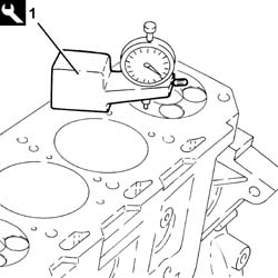
1. Measure the piston projection in two places at 180° on the gudgeon pin axis using the tool and take the average of the two values measured for each piston.


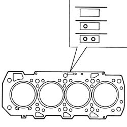
- Select the correct size cylinder head gasket, according to the maximum value of the averages for the protrusion of each individual piston.


Measurement


Value


Validity


Cylinder head gasket size with maximum piston projection (mm)


projection

+0.110 ÷ +0.230

thickness (no opening)

0.95 ± 0.05


2.0 JTD 115 HP


Measurement


Value


Validity


Cylinder head gasket size with maximum piston projection (mm)


projection

+0.231 ÷ +0.330

thickness (one opening)

1.05 ± 0.05


2.0 JTD 115 HP


Measurement


Value


Validity


Cylinder head gasket size with maximum piston projection (mm)


projection

+0.331 ÷ +0.425

thickness (two openings)

1.15 ± 0.05


2.0 JTD 115 HP

Position the first cylinder at TDC; rotate the crankshaft a further two teeth of the toothed timing drive pulley to lower the pistons, thereby preventing any interference with the valves whilst fitting the cylinder head.

- Position the cylinder head locating bushes on the engine block as shown in the figure.

The locating bushes between the engine block and cylinder head are shorter (12.5 mm) than the bushes between the cylinder head and the camshaft housing. Take great care not to reverse them as this could impair engine operation.


- Fit the new cylinder head gasket selected.

- Position the cylinder head on the engine block.

Do not reuse the cylinder head screws more than four times because they undergo permanent lengthening whenever they are tightened.

Replace the screws if the number of times that the screws have been tightened to the cylinder heads is unknown.

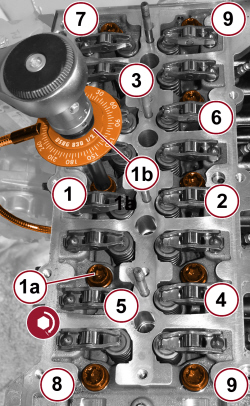
1. Tighten the cylinder head screws (1a) to the prescribed torque using the angular tightening tool (1b).


Component


Fixing


Ø


Value (daNm)


Validity


Cylinder head


Screw


M12


6.2÷6.9 + 86°÷94° + 86°÷94° + 86°÷94°


2.0 JTD 115 HP


Tool


Denomination


Function


Validity


1.895.897.001


Torque wrench


Angular torque tightening


2.0 JTD 115 HP

Reach the figure of 6.5 daNm by pretightening to 2.0 daNm subsequently increasing by a torque of 4.5 daNm to achieve the rated value of 6.5 daNm.

Follow the order shown in the figure for each tightening sequence.

- Fit the pressure pump mounting complete with pressure pump back in its housing and secure it by tightening the screws to the prescribed torque.


Component


Fixing


Ø


Value (daNm)


Validity


Pressure pump support - engine block side


Upper screw (pretreated with sealant - to be replaced)


M8 x 1.25 x 110


2.3 ÷ 2.8


2.0 JTD 115 HP


Component


Fixing


Ø


Value (daNm)


Validity


Pressure pump support - engine block side


Screw


M8 x 1.25 x 35


2.3 ÷ 2.8


2.0 JTD 115 HP


Component


Fixing


Ø


Value (daNm)


Validity


Pressure pump support - cylinder head side


Screw


M10 x 1.25 x 40


4.5 ÷ 5.5


2.0 JTD 115 HP

- Place the alternator in position and tighten the screws to the prescribed torque.


Component


Fixing


Ø


Value (daNm)


Val.


Alternator


Screw


M12x1.75


6.3 ÷ 7.7


2.0 JTD 115 HP


Component


Fixing


Ø


Value (daNm)


Val.


Alternator reaction bracket


Screw


M12x1.75


6.3 ÷ 7.7


2.0 JTD 115 HP

- Place the engine oil filter-heat exchanger mounting in position complete with new O-rings and tighten the screws.


Component


Fixing


Ø


Value (daNm)


Validity


Engine oil heat exchanger


Screw (to be replaced)


M10


4.1 ÷ 5.0


2.0 JTD 115 HP

- Place the power steering pump-air conditioning mounting in its housing and tighten the screws to the prescribed torque.


Component


Fixing


Ø


Value (daNm)


Val.


Power steering pump/compressor mounting to crankcase


Screw


M10x1.25


4.5 ÷ 5.5


2.0 JTD 115 HP

- Place the power steering pump in its seat and tighten the screws to the prescribed torque.


Component


Fixing


Ø


Value (daNm)


Val.


Power steering pump


Screw


M8x1.25


2.3 ÷ 2.8


2.0 JTD 115 HP

- Place the air conditioning in its housing and tighten the screws to the prescribed torque.

- Place the coolant supply pipe to the engine oil heat exchanger in position and connect the quick connectors.

- Place the coolant outlet pipe from the engine oil heat exchanger in position and connect the quick connectors.

- Connect the fuel return pipe to the pressure pump, pressure pump side and tighten the band.


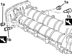
1. If not already carried out during cylinder head overhaul, remove the plugs (1a) and fit the camshaft timing adjustment tools (1b) to the camshaft housing.

Check that the tools are correctly fitted in the housings in the camshafts.


Tool


Denomination


Function


Validity


1.870.896.900


Template


Engine tuning


2.0 JTD 115 HP


- Place the camshaft housing locating bushes on the cylinder head.

The locating bushes between the cylinder head and the camshaft housing are longer (16.0 mm) than those between the engine block and the cylinder head; take care therefore not to mix them up because this could adversely affect the operation of the engine.

- Place the camshaft housing gasket in position.

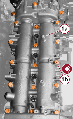
1. Position the cylinder head extension assembly (1a) in its housing and secure it by tightening the screws (1b) to the prescribed torque.


Component


Fixing


Ø


Value (daNm)


Validity


Camshaft housing


Screw


M8


2.3 ÷ 2.8


2.0 JTD 115 HP

- Refit the air chamber connecting bracket to the cylinder head extension in place and tighten the screws to the prescribed torque.


Component


Fixing


Ø


Value (daNm)


Validity


Reaction bracket on head


Screw


M10


4.5 ÷ 5.5


2.0 JTD 115 HP


Component


Fixing


Ø


Value (daNm)


Validity


Reaction bracket on manifold


Screw


M6


0.8 ÷ 1.0


2.0 JTD 115 HP

- Place the pipe and wiring mounting bracket in position and secure it tightening the screws to the prescribed torque.


- If this has not already been carried out during the overhauling of the cylinder head, loosen the screw fixing the exhaust side camshaft drive toothed pulley.

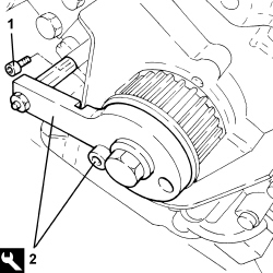
1. Undo the screw securing the engine block front cover shown in the figure.

2. Fit the tool.

The crankshaft must be rotated, using small movements, to allow the locating dowel on the timing drive pulley to be inserted in the opening in the tool.


Tool


Denomination


Function


Validity


2.000.003.000


Template


Engine tuning


2.0 JTD 115 HP


- Remove the crankshaft timing template fitted previously.

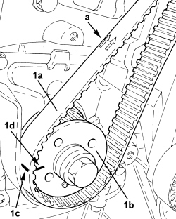
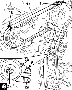
1. Fit the toothed timing drive belt (1a) on the drive toothed pulley (1b), taking care to ensure that the yellow reference (1b) on it is aligned with the notch (1d).

The yellow reference (1c) on the toothed timing belt is next to the two yellow arrows (a).


1. Fit the toothed timing drive belt (1a) completely, taking care to ensure that the yellow references (1b) on it are aligned with the references on the toothed pulleys.

2. Use a screwdriver to lever in opening (2a) until the reference for the tensioner (2b) is in the maximum tension position; then, tighten the screws (2c) for the tensioner to the prescribed torque in this position.

The opening "a" is the reference for the definitive tensioning of the toothed timing drive belt described below.


Component


Fixing


Ø


Value (daNm)


Validity


Timing control moving tensioner


Screw


M6


2.3 ÷ 2.8


2.0 JTD 115 HP

- Tighten the screw fixing the exhaust side camshaft toothed pulley to the prescribed torque using the tools for counter-torque.


Component


Fixing


Ø


Value (daNm)


Validity


Driven timing toothed pulley


Screw


M12


2.9 ÷ 3.2 + 35° ÷ 42°


2.0 JTD 115 HP


Tool


Denomination


Function


Validity


1.870.815.000


Counter-torque


Loosen/tighten timing driven toothed pulley screw


2.0 JTD 115 HP


Tool


Denomination


Function


Validity


1.870.836.000


Pins


Loosen/tighten timing driven toothed pulley screw


2.0 JTD 115 HP

- Remove the timing tools.


Tool


Denomination


Function


Validity


1.870.896.900


Template


Engine tuning


2.0 JTD 115 HP


Tool


Denomination


Function


Validity


2.000.003.000


Template


Engine tuning


2.0 JTD 115 HP

- Rotate the crankshaft through two revolutions.

- Loosen the screw retaining the moving timing tensioner.

- Use a screwdriver for leverage on the tensioner arm until the reference for the tensioner is in line with the reference opening and tighten the tensioner screw to the prescribed torque in this position.


Component


Fixing


Ø


Value (daNm)


Validity


Timing control moving tensioner


Screw


M6


2.3 ÷ 2.8


2.0 JTD 115 HP

- Recheck the timing by refitting the timing tools.


Tool


Denomination


Function


Validity


1.870.896.900


Template


Engine tuning


2.0 JTD 115 HP


Tool


Denomination


Function


Validity


2.000.003.000


Template


Engine tuning


2.0 JTD 115 HP

- Remove the tool for the crankshaft rotation.


Tool


Denomination


Function


Validity


1.860.815.000


Flange


Crankshaft rotation


2.0 JTD 115 HP

- Tighten the screw fixing the previously removed engine block front cover.


Component


Fixing


Ø


Value (daNm)


Validity


Crankshaft oil seal front cover


Screw (to be replaced)


M6


0.8 ÷ 1.0


2.0 JTD 115 HP

- Tighten the plugs in the cylinder head extension for fitting the timing tools.


Component


Fixing


Ø


Value (daNm)


Validity


Plugs for timing holes on camshaft housing


-


M16


1.4 ÷ 1.7


2.0 JTD 115 HP

- Fit the power unit rigid support and tighten the screws to the prescribed torque.


Component


Fixing


Ø


Value (daNm)


Validity


Timing side power unit rigid mounting to automatic tensioner support mounting


Screw


M10


4.5 ÷ 5.5


2.0 JTD 115 HP


Component


Fixing


Ø


Value (daNm)


Validity


Timing side power unit rigid mounting to automatic tensioner support mounting


Screw


M8


2.3 ÷ 2.8


2.0 JTD 115 HP


Component


Fixing


Ø


Value (daNm)


Validity


Timing side power unit rigid mounting to injection pump mounting


Screw


M8


2.3 ÷ 2.8


2.0 JTD 115 HP

- Place the timing drive belt protective cover in its housing and tighten the screws to the prescribed torque.


Component


Fixing


Ø


Value (daNm)


Validity


Timing belt guard


Screw


M6


0.8 ÷ 1.0


2.0 JTD 115 HP

- Position the auxiliary drive belt moving tensioner in its housing and secure it by tightening the screw to the prescribed torque.


Component


Fixing


Ø


Value (daNm)


Validity


Engine component single belt moving tensioner on injection pump mounting


Screw


M10x1.5x68


4.5 ÷ 5.5


2.0 JTD 115 HP

- Position the service pulley on the crankshaft in its housing and tighten the screws to the prescribed torque.


Component


Fixing


Ø


Value (daNm)


Validity


Service pulley on crankshaft


Screw


M8


2.7 ÷ 3.3


2.0 JTD 115 HP

- Fit the auxiliary drive belt using the automatic tensioner.


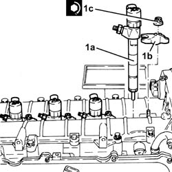
1. Fit the injectors (1a) in their seats complete with brackets (1b) and tighten the nuts (1c) to the prescribed torque.

Start the refitting beginning with the injector for cylinder no. 4 and continue with the injectors for cylinders 3, 2, and 1.


Component


Fixing


Ø


Value (daNm)


Validity


Injector brackets


Nut


M8


2.3 ÷ 2.8


2.0 JTD 115 HP

- Connect the brake servo vacuum pipe to the vacuum pump.

- Fit the pipe from the injectors to the fuel recovery manifold and connect to the fuel recovery manifold.

- Connect the pipe from the injectors to the fuel recovery manifold, injector side, pushing it until the clips click into place.


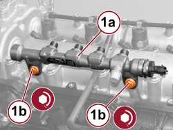
1. Place the single fuel manifold pipe in its housing and tighten the screws (1b) to the prescribed torque.


Component


Fixing


Ø


Value (daNm)


Validity


Single fuel manifold pipe (rail)


Screw


M8


2.3 ÷ 2.8


2.0 JTD 115 HP


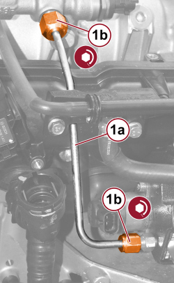
1. Place the pipe (1a) from the pressure pump to the fuel manifold back in its housing and secure it by tightening the connectors (1b) to the prescribed torque.


Component


Fixing


Ø


Value (daNm)


Validity


Pipes from pressure pump to fuel manifold - fuel manifold side


Connector


M14


1.8 ÷ 2.0


2.0 JTD 115 HP


Component


Fixing


Ø


Value (daNm)


Validity


Pipe from pressure pump to fuel manifold - pressure pump side


Connector


M12


2.2 ÷ 2.4


2.0 JTD 115 HP


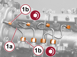
1. Place the pipes (1a) from the fuel manifold to the injectors in their housings and secure them by tightening the connectors (1b) to the prescribed torque.


Component


Fixing


Ø


Value (daNm)


Validity


Pipes from fuel manifold to injectors - fuel manifold side


Connector


M14


1.8 ÷ 2.0


2.0 JTD 115 HP


Component


Fixing


Ø


Value (daNm)


Validity


Pipes from fuel manifold to injectors - injectors side


Connector


M12


2.2 ÷ 2.4


2.0 JTD 115 HP

- Refit the degassing pipe in its housing, connect it to the thermostat and tighten the band.

- Tighten the screw fixing the degassing pipe to the pressure pump mounting.

- Place the oil vapour separator complete with oil return pipe to the sump in its housing and tighten the screws.

- Tighten the screws fixing the oil vapour pipe to the air chamber and to the camshaft housing.

- Connect the oil vapour recovery pipe to the separator and tighten the band.

- Place the new exhaust manifold gasket in its housing.


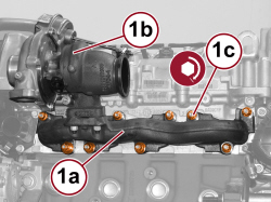
1. Place the exhaust manifold (1a) with turbocharger (1b) assembly in its housing, insert the spacers and tighten the nuts (1b) to the prescribed torque.


Component


Fixing


Ø


Value (daNm)


Validity


Turbocharger to exhaust manifold


Nut (to replace)


M8


2.3 ÷ 2.8


2.0 JTD 115 HP

- Fit a new O-ring on the connector for the engine oil return pipe from the turbocharger, engine block side.

- Fit a new gasket attaching the retaining tabs to the connector for the engine oil return pipe from the turbocharger, turbocharger side.


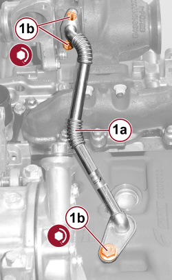
1. Place the engine oil return pipe (1a) from turbocharger in its housing and tighten the connector fixing screws (1b) to the prescribed torque.


Component


Fixing


Ø


Value (daNm)


Validity


Engine oil return pipe to turbocharger


Screw


M10


4.5 ÷ 5.5


2.0 JTD 115 HP


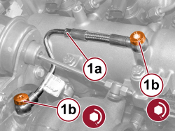
1. Place the turbocharger engine oil supply pipe (1a) in its housing complete with new gaskets and tighten the connectors (1b) to the prescribed torque.


Component


Fixing


Ø


Value (daNm)


Validity


Engine oil supply pipe to turbocharger


Connector


M10


1.4 ÷ 1.7


2.0 JTD 115 HP

- Position the pipe from turbocharger to intercooler, with sleeve, then tighten the turbocharger fixing screws.

- Connect the vacuum pipe.

- Fit the oil dipstick pipe in the hole inside the crankcase and tighten the bracket fixing screw.


Component


Fixing


Ø


Value (daNm)


Validity


Oil dipstick tube to crankcase


Screw


M8


2.3 ÷ 2.8


2.0 JTD 115 HP

- Place the oil level dipstick in the pipe.

- Place the engine wiring in position and secure it to the retaining clips.

- Tighten the screw fixing the wiring duct to the cylinder head extension and to the intake manifold.

- Connect the electrical connections for the injectors.


Description


Connector


-


Injector


See N070

- Tighten the fixing screws securing the injector wiring duct to the cylinder head extension.

- Connect the electrical connection for the differential pressure sensor upstream and downstream of the particulate filter.


Description


Connector


-


Particulate filter differential pressure sensor


See K187

- Connect the electrical connection for the fuel pressure regulator on the pressure pump.


Description


Connector


-


Fuel pressure regulator


See N077

- Connect the electrical connection for the air temperature and pressure sensor.


Description


Connector


-


Air pressure/temperature sensor


See K044

- Connect the heater plug electrical connections.


Description


Connector


-


Heater plugs


See A040

- Connect the electrical connection for the fuel pressure sensor.


Description


Connector


-


Fuel pressure sensor


See K083

- Connect the alternator earth lead and tighten the nut.


Description


Connector


-


Alternator


See A010

- Connect the electrical connection for the engine oil pressure switch.


Description


Connector


-


Engine oil pressure sensor (switch)


See K030

- Connect the electrical connection for the rpm sensor.


Description


Connector


-


Rpm sensor


See K046

- Connect the electrical connection for the engine oil level sensor.


Description


Connector


-


Engine oil level sensor


See K032

- Connect the electrical connection for the EGR solenoid.


Description


Connector


-


EGR solenoid


See L030

- Connect the electrical connection for the throttle body.


Description


Connector


-


Integrated throttle body actuator


See N075

- Connect the electrical connection for the engine coolant temperature sensor.


Description


Connector


-


Engine coolant temperature sensor/sender unit


See K036

- Connect the electrical connection for the EGR heat exchanger water supply actuator solenoid valve.


Description


Connector


-


EGR heat exchanger water supply actuator control solenoid


See L103

- Connect the electrical connection for the timing sensor.


Description


Connector


-


timing sensor


See K047

- Place the harness with exhaust gas temperature sensor in place, tighten the retaining clip and engage the connector in the holding bracket.

- Connect the electrical connection for the exhaust gas temperature sensor.


Description


Connector


-


UPSTREAM PARTICULATE FILTER TEMPERATURE SENSOR (DPF)


See K189

- Connect the electrical connection for the A/C system compressor engagement electromagnet.


Description


Connector


-


Air conditioning compressor engagement electromagnet


See L020

- Position in its housing the coolant return pipe from the radiator with the supply pipe from coolant reservoir to water pump and tighten the band.

- Place the duct with fuel supply pipes in its housing and tighten the fixing screws.

- Secure the fuel supply and return pipes with the retaining clips.

- Connect the fuel supply pipe quick connector to the pressure pump and the fuel return pipe quick connector to the return manifold.

- Position the water return pipe from the heater in its housing, connect the quick connector and tighten the band.

- Position the water supply pipe to the heater in its housing, close the band and engage it in the retaining clips.

- Tighten the drain plug in the crankcase sump to the prescribed torque.


When the refitting of the power unit is completed, refill the engine lubrication system.

    Op. 1004D40 ENGINE - POSITION ON STAND AND REMOVE